Calculating Interference for the CommSystem
Use the Basic Interference page to make the following specifications:
- Choose whether or not to calculate the effect of interference emanating from sources identified on the IF Sources page. Enable this calculation by selecting the Calculate Interference check box.
- Specify how to calculate interference by selecting the Reference Bandwidth value for STK to use in reporting power flux density.
- Choose whether or not to calculate the effect of interference emanating from sources identified on the Receiver Basic Definition properties page. Enable this calculation by selecting the Include Receiver Interference Emitters check box.
For more detailed information about Power Flux Density, see Technical Notes.
Interference analysis methods
When working in the ITU (International Telecommunications Union) framework, the key figure of interest is the equivalent power flux density (epfd) at the receivers. STK measures epfddown on the ground on the basis of the contribution of the interference sources. The epfddown includes the gain discrimination of the receiver. The epfdup is measured at the satellite and includes the receiver gain discrimination.
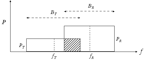
The interference analysis gives the power flux density relative to a reference bandwidth, typically 4 kHz, 40 kHz, or 1 MHz when reporting or graphing the results. The interference analysis method takes into account the bandwidth of the receiver as well as that of the interfering transmitter and includes only the overlap (if any exists) between these two in the denominator when calculating carrier-to-noise ratio. The difference is illustrated in the following graph showing power, frequency. and bandwidth for a receiver R and an interfering transmitter T.
Interference analysis methods
The ITU method uses only the overlap between the transmitter and receiver bandwidths (the shaded area in the figure).
Power Spectral Density and Spectral Filtering
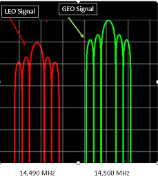
The Power Spectral Density (PSD) option enables the scenario to model the actual spectral shape of the transmitted signal based on the modulation, data rate, etc. The use of Spectral Filters on transmitters modifies the spectral shape. The use of Spectral Filters on the receiver helps reduce the impact of out-of-band signals from jammers and other sources.
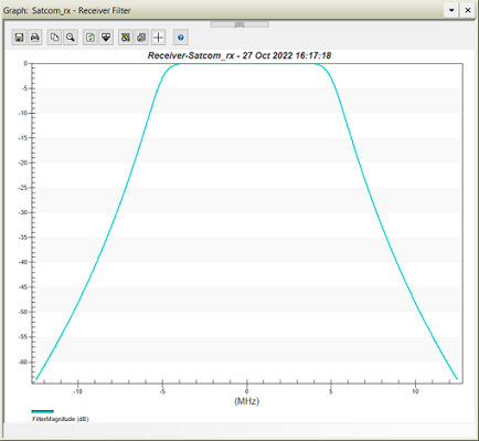
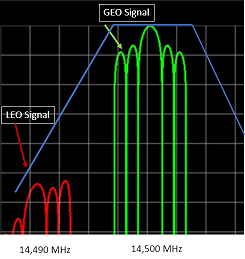
Example Illustration of applying an eighth-Order Butterworth Filter with 5 MHz Cutoff Centered at 14.5 GHz