STK Pro
The results of the tutorial may vary depending on the user settings and data enabled (online operations, terrain server, dynamic Earth data, etc.). It is acceptable to have different results.
Capabilities Covered
This lesson covers the following STK Capabilities:
- STK Pro
Problem Statement
It is said that the Molniya orbit is a great way to spy on the United States. During such a spacecraft’s two (2) twelve (12) hour daily orbits, how many hours a day can a Molniya satellite actually see Washington?
Break It Down
You have some information that may be helpful. Here’s what you know:
- There are two “players” in the scenario--a spacecraft traveling in a Molniya orbit and the city of Washington.
- A Molniya orbit has two (2) twelve (12) hour daily orbits.
- You want to know if and when a Molniya satellite can “see” Washington.
Solution
Build an STK scenario that allows you to calculate a simple line-of-sight access between a spacecraft traveling in a Molniya orbit and Washington, D.C. so that you can tell at what points along the spacecraft’s orbit it can “see” Washington.
Video Guidance
Watch the following video. Then follow the steps below, which incorporate the systems and missions you work on (sample inputs provided).
Welcome to STK
The first thing you need to do is launch STK, and create a new scenario.
- Double-click the STK icon (
 ) on the desktop.
 - Click the Create a Scenario button.
- Clicking the New button (
 ) on the Default toolbar, or
 - Selecting the New () option from the File menu.
- Clicking Ctrl + N on the keyboard.
- Click the Create a New Scenario button.
Everything in STK begins with a scenario. A scenario is STK's name for an instance of an analytical or operational task being modeled using STK. In STK a scenario is represented by an icon of an idealized “scene”. The STK scenario creates the context, or environment, within which all other objects in the scenario exist. You can create an unlimited number of scenarios with STK, however only one scenario can be open at a time.
When STK launches, the Welcome dialog will appear. Using the options available here, you can create new scenarios, open existing scenarios, access the STK Help System, or exit the STK application.
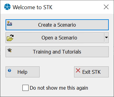
Welcome dialog
The Welcome dialog also provides an option to disable this feature in the event that you prefer to create and manage scenarios manually. If the Welcome dialog were disabled, you could create a new scenario by either:
Model the World!
When you click the Create a New Scenario button, the New Scenario Wizard appears. You can input basic information about the scenario here. Let’s set the basic parameters for scenario creation now.
- Enter the following in the New Scenario Wizard.
| Option | Value |
|---|---|
| Name | See_DC |
| Description | Can a Molniya satellite spy on Washington, D.C.? |
| Location | C:\Users\<username>\Documents\STK 12\ |
| Start & Stop (Analysis Period) | Leave the default analysis period, which is noon today local time displayed as UTCG (based on your computer time zone) + 24 hours. |
Analysis Period
Every scenario requires that you define the times during which the conditions that you set for your world, and the objects in your world, will be relevant. The analysis period defines the epoch and the start and stop times of your scenario. The analysis period defines the general time span (a range of several hours, days, or weeks) for analysis.
By default, times are displayed in UTCG. That being the case, the analysis period will vary based on the time zone to which your computer is set. You can change the time unit to LCLG to display the analysis period in your current local time. Let’s try it.
- Click the Extend (
 ) button beside the scenario time.
 - Extend the Start Time menu.
- Extend the Units menu.
- Select LCLG from the menu that appears.
- What is the current local time?
- When you finish, click OK to dismiss the New Scenario Wizard.
- When the scenario loads, click Save (
 ).
). - Verify the scenario name and location and click Save.
STK provides a user-editable default analysis period for every new scenario. Since you are not concerned with determining when Molniya can see Washington, D.C. on a specific day at a specific time, but are instead just doing some general analysis, you can accept the default analysis period for this example.
Once a scenario is saved the first time, it will be saved to the same location every time you click the Save button. The Save button is always available, and always saves the entire scenario, regardless of the window or object that is selected.
Scenarios
The scenario itself is saved as an object (*.sc) and each object within the scenario (e.g., satellites, facilities, planets, stars, receivers and transmitters, etc.) is saved individually.
Object Browser
When you create a new scenario, STK updates the Object Browser to include the new scenario and creates the appropriate visualization windows. Once in the Object Browser the objects can be named and properties can be applied.
Get Off on the Right Foot -- Stay Organized
Once you begin working with STK, you may create and save several scenarios with many objects in a short time. The most helpful technique to manage your scenario files is to save each scenario into its own folder, and give the folder and the scenario file (*.sc) the same name as in the example above. You’ll find that this simple rule of thumb will help you to manage your scenarios more efficiently for the following reasons:
- It decreases the likelihood that you will accidentally overwrite your previous work, especially if you have objects with the same names in different scenarios (e.g. several satellites named LEO).
- It helps keep your work organized, so that it is easier to find a given scenario later.
- It makes it easier to share your scenarios with others.
When you use the New Scenario Wizard, STK will automatically create a new directory in your default user directory (C:\Users\<username>\Documents\STK 12\) with the same name that you input for the scenario name. STK will then store all of your scenario files as described above. While the new directory is created, the scenario is not saved to that directory until you actually perform the save function. When you save a scenario in STK, it will save in the format in which it originated. In other words, if you open a VDF, the default save format will be a VDF. The same is true for a scenario file (*.sc). If you want to save a VDF as a scenario file (or vice-versa), you must change the file format when you are performing the Save As procedure.
The Properties Browser
Each STK object and visualization window has its own set of properties, which are organized into categories (e.g., Basic, 2D Graphics, Constraints, etc.). Customizing properties creates a meaningful environment for the other objects in your scenario. The properties used to define STK objects are organized in the Properties Browser. When you open the Properties Browser you will see the properties for whatever object or visualization window is selected in the STK Workspace.
Accessing Object Properties
There are several ways to access object and window properties. You can access object properties in one of the following ways:
- Double-click the object in the Object Browser.
- Right-click the object in the Object Browser or visualization window (2D or 3D), and select Properties (
 ) from the menu that appears.
 - Select an object in the Object Browser, and click the Properties () button.
Scenario Basic Properties
Scenario properties customize the conditions of your scenario. Customizing properties creates a meaningful environment for the other objects in your scenario. Take a look at the rest of the scenario Basic properties.
- Double-click See_DC () in the Object Browser to open its properties ().
- Select the Time page.
- Are the Start and Stop times set to those that you set when you created the scenario?
- Select the Description page.
- Is the description that you provided when you created the scenario in the Description page?
- When you finish, click Cancel to dismiss the scenario properties without making any changes.
| Properties | Description |
|---|---|
| Time | Define the epoch and start and stop times that apply throughout the scenario. Control the animation cycle, animation step definition, and the intervals between refresh updates in the graphics windows. Values set here can be overridden at the subordinate level for certain objects. |
| Units | Establish the default settings for all units of measure used for display and data input purposes in a scenario. Selections made here can be overridden locally for a specific object or for an entire class of objects. |
| Database | Set defaults for available databases. |
| Earth Data | Select an Earth Orientation Parameters (EOP) file. |
| Terrain | Import and display terrain elevation data for facility and target azimuth-elevation mask and position. |
| Global Attributes | Allows the configuration of warning messages for missiles, satellites, and Aviator objects. |
| Description | Record useful information about your scenario. |
Insert STK Objects Tool
When a scenario is created, the Insert STK Objects tool appears automatically unless the Do not show me this again option is enabled. From here, you can begin the object creation and insertion process. The Insert STK Objects tool makes it easy to insert and configure some of the most commonly used individual objects. The left-hand pane lists commonly used STK objects. When you select an object on the left, all of the methods available for introducing that class of object will be listed on the right. The process and data that you will have to provide will depend on the object class and introduction method selected.
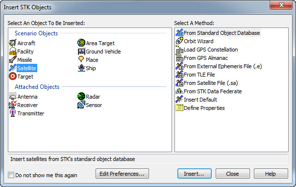
Insert STK Objects tool
The Insert STK Objects tool can be customized using the options available on the New Object page of the Application Preferences.
- Click the Edit Preferences... button.
- Select the New Object page.
- Locate the Define Default Creation Methods area.
- When you finish, click Cancel to dismiss the New Object preferences page.
The Objects list contains all of the available object in STK. When an object is selected, all of the available methods for creating and configuring that object display in the Method list to the right. You can include or exclude options from the Insert STK Objects tool by selecting them in the list and enabling or disabling the Show object in insert new object tool.
Model a Spacecraft
Now you have a model of a meaningful “world”, but your world has no objects. You still need a spacecraft traveling in a Molniya orbit. In STK, the satellite object is used to model the properties and behavior of a vehicle in orbit around a central body.
- Select the following in the Insert STK Objects tool (
 ):
): - Click the Insert... button.
| Option | Value |
|---|---|
| Select an Object to be Inserted: |
|
| Select a Method |
|
When you click the Insert... button, the Orbit Wizard will appear.
The Orbit Wizard
The Orbit Wizard is a satellite level tool designed to assist you in creating any one of several standard orbits or designing your own satellite orbit. The configurable options available will depend on the orbit Type selected. The orbit types available are outlined below.
| Orbit | Description |
|---|---|
| Circular | Circular orbits have a constant radius. |
| Critically Inclined | Critically Inclined orbits maintain perigee at a fixed latitude. The line of apsides does not change over time. |
| Critically Inclined, Sun Sync | Critically Inclined Sun Synchronous orbits combine the features of both basic types of orbits. The orbit uses a retrograde inclination of 116.565 degrees. The satellite will pass overhead at the same local mean solar time for each revolution and has a perigee which remains at a fixed latitude. |
| Geosynchronous | A satellite in a stationary orbit will remain fixed in the sky above the specified fixed longitude. |
| Molniya | Molniya orbits are highly eccentric, meaning that there is a large difference between the altitude at apogee and the altitude of perigee. Molniya orbits are also critically inclined. This keeps the perigee of the orbit in the Southern Hemisphere. Molniya orbits also have a long dwell time in the extreme latitude regions of the Northern Hemisphere. |
| Orbit Designer | With this option, you can create any orbit you wish. |
| Repeating Ground Trace | Orbits with repeating ground traces are useful when identical viewing conditions are desired at different times to detect changes. The ground trace may be caused to repeat every day or to interweave from day to day before repeating. |
| Repeating Sun Sync | Sun Sync orbits with repeating ground traces are useful when identical viewing and lighting conditions are desired at different times to detect changes. The ground trace may be caused to repeat every day or to interweave from day to day before repeating. The orbit repeats the ground coverage cycle and passes overhead at approximately the same local mean solar time for each revolution. |
| Sun Synchronous | These orbits are designed to utilize the effect of the Earth's oblateness, causing the orbit plane to precess at a rate equal to the mean orbital rate of the Earth around the Sun. Sun synchronous orbits have the property that their nodes maintain constant local mean solar times. |
No matter which Type of orbit you select, the Orbit Wizard lets you change the satellite analysis period as well as configure and preview satellite graphics before the object is introduced into the scenario.
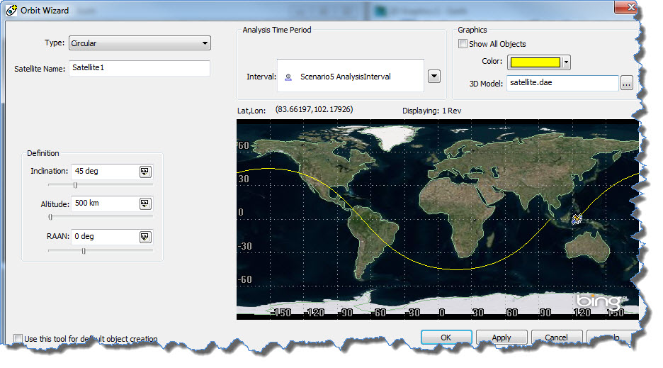
Orbit Wizard
- When the Orbit Wizard appears, select the following:
- Accept all other default values.
- Click OK.
| Option | Value |
|---|---|
| Type | Molniya |
| Satellite Name | SpySat |
View in 3D
Now that you have a satellite in the scenario and in a Molniya orbit, let's take a look at it.
- Right-click on SpySat (
 ) in the Object Browser.
 - Select Zoom To.
This model is a glTF (GL Transmission Format), which is a file format for 3D scenes and models using the JSON standard. The intention is that glTF be an efficient, interoperable asset delivery format that compresses the size of 3D scenes and minimizes runtime processing by applications using WebGL and other APIs. STK comes with a few installed glTF models that can be accessed in the 3D Graphics - Model properties of any object. To learn more about glTF models in STK, click here.
Model Washington
It looks like you have one more object to model--Washington. STK provides three objects that can be used to model a point-of-interest on the surface of the central body-- Places (![]() ), Facilities (
), Facilities (![]() ) and Targets (
) and Targets (![]() ). The Place object models a point of interest on the surface of the central body. Facilities and targets are almost identical in properties and behavior. Often, facilities and targets are used to differentiate between friendly and unfriendly sites, where a facility marks a friendly site, and a target marks a unfriendly site.
). The Place object models a point of interest on the surface of the central body. Facilities and targets are almost identical in properties and behavior. Often, facilities and targets are used to differentiate between friendly and unfriendly sites, where a facility marks a friendly site, and a target marks a unfriendly site.
Insert a Place
Facilities can be positioned and repositioned in a variety of ways. For this example, you’ll use an entry from the STK City Database.
- Return to the Insert STK Objects tool ().
- Select the following:
- Click the Insert... button.
| Option | Value |
|---|---|
| Select an Object to be Inserted: |
|
| Select a Method |
|
The STK City Database
Several comprehensive databases are shipped with STK for your use. The City Database contains thousands of cities around the world. Individual city information includes the exact location of the city. You will use the City Database tool to model Washington, D.C.
- When the City Database Search tool appears, set the following:
- Click Search.
- When the search results appear, select Washington (City Name) District of Columbia (Province).
- Click the Insert button.
- Close the City Database Search tool.
- You don’t need to create any more objects, so you can close the Insert STK Objects tool () now if you like.
| Option | State | Value |
|---|---|---|
| City Name | On | Washington |
| Province | Off | N/A |
| Country | Off | N/A |
When a predefined object is imported from an STK databases (satellite, facility, city or star), information about that object is automatically written to its Long Description.
2D and 3D Visualization
Two of the most powerful and indispensable STK tools are the 2D and 3D Graphics (STK Free Basic edition) windows. Using them, you can visualize your scenario in a dynamic 2D and/or 3D environment. Time can be animated forward, backward, and in real-time to display space- and ground-based object positions, coverage areas, visibility status, lighting conditions, and much more.
- Bring the 2D Graphics window to the front.
- Advance the animation (
 ) a few steps until SpySat () is clearly visible.
 - Bring the 3D Graphics window to the front.
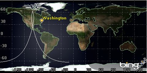
2D View: SpySat position
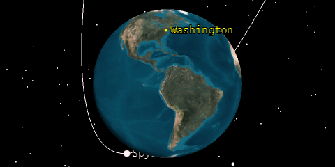
3D View: SpySat position
SpySat’s object marker is positioned according to the current animation time in both windows, and its ground (2D) and orbit tracks (2D and 3D) are clearly visible.
Removing Object Graphics
There is a quick way to enable and disable the object graphics in the 2D and 3D Graphics window.
- Select SpySat () in the Object Browser.
- Click the Toggle On/Off (
 ) button in the Object Browser.
 - Disable SpySat’s () graphics by clicking the check mark beside the satellite. This will toggle the graphics on/off.
- Do you notice that the orbit and satellite icon disappear?
- Do you notice that only the satellite marker and label disappear? Why is this?
- Enable SpySat’s () graphics.
Animation Properties
Animation properties are part of the Scenario Basic - Time properties. Using Animation properties you can define the animation cycle, step definition and the intervals between refresh updates in the 2D and 3D Graphics windows.
Animation Cycle
The animation cycle defines a portion of the scenario that you wish to see in motion when you animate. Movement of objects within a scenario during any portion of the analysis period that do not fall within the animation cycle will not display in the visualization windows.
- Play () the animation, and watch as Molniya () travels along its path.
- Pause (
 ) the animation at any point.
Mouse Around in 2D
You can use the mouse to move around in the 2D Graphics window. Use the mouse to slide the 2D Graphics window to get a better look at an area of interest.
- Click and hold the left mouse button, then move your mouse around in the 2D Graphics window to move the focal point.
Zoom To SpySat
STK provides tools for changing your perspective in the 3D Graphics window. It is often helpful to view the events in a scenario from the perspective of a particular object. Use the Zoom To to center the view in the 3D Graphics window on SpySat, and get a better look at the satellite model.
- Bring the 3D Graphics window to the front.
- Right-click SpySat in the Object Browser or in the 3D Graphics window.
- Select Zoom To.
- Check the 3D Graphics window. SpySat () is now the focal point.
Mouse Around in 3D
You can use the mouse to move around in the 3D Graphics window. Use the mouse to zoom and rotate in the 3D Graphics window to get a better look at the satellite object model.
- Click and hold the left mouse button, then move your mouse around in the 3D Graphics window to rotate the focal point.
- Click and hold the right mouse button, then move your mouse forward and backward to zoom in and out.
- If your mouse has a click wheel, you can use that to zoom in and out on the 3D Graphics window.
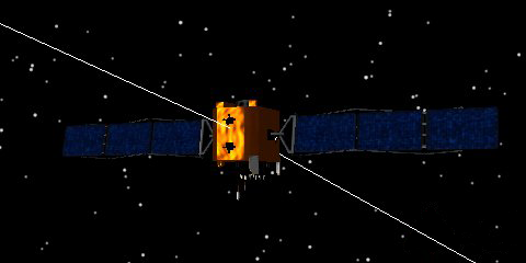
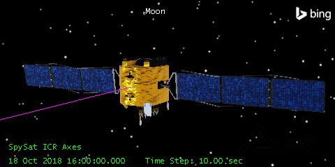
3D View: SpySat model
In the 3D Graphics window, SpySat is represented by a 3D model.
You can also focus the 3D Graphics window on an object-of-interest by holding down Shift on your keyboard and double-click on the object-of-interest in the 3D Graphics window.
Restore the View
- Reset (
 ) the animation.
 - Select the 3D Graphics window, and click the Home View button (
 ) on the 3D Graphics toolbar to restore the default Earth-centered view.
 - Select the 2D Graphics window, and click the Zoom Out button (
 ) on the Default toolbar as many times as necessary to return the map to its original view.
Report Positional Data
Using the visualization windows, you were able to see the location of SpySat and watch its position change over time, but suppose you needed more detailed data about how SpySat’s position or orbital parameters will change over time?
STK includes a number of Data Provider tools with which you can report and display data about objects in one of the four available formats--Report, Dynamic Display, Graph, or Strip Chart.
- Click the Report & Graph Manager button (
 ) on the STK Tools toolbar.
 - Select the following:
- Click Generate...
- Using the data in the report, answer the following:
- What is the inclination of SpySat over time?
- When you finish, close the Classical Orbit Elements report.
- Close the Report & Graph Manager ().
| Option | Value |
|---|---|
| Object Type | Satellite |
| Object (Below Object Type) | SpySat |
| Show Reports | On |
| Show Graphs | Off |
| Style | Classical Orbit Elements |
| Generate As | Report/Graph |
STK will generate and display a text report that provides a representation of the SpySat’s orbital elements.
When Can SpySat “See” Washington?
You have added two objects to your scenario--one satellite object representing SpySat and one place object representing Washington, D.C. Now, you need to determine when Washington, D.C. is within the SpySat’s line of sight.
Calculating object-to-object visibility in STK is called access. STK will calculate the times one object can access, or “see”, another object based on position and availability information that considers timing and constraints if necessary. An access is defined by the two objects for which the access is computed and is calculated FROM the object that is “looking” for another object TO the object that it is “looking for”. Once an access is calculated, it maintains a close relationship with the defining objects. If either of the defining objects is changed in such a way that the access times may be altered, the access is automatically recomputed. Also, if either of the defining objects is removed from the scenario, the access is automatically removed.
Now determine when SpySat can “see” Washington by calculating a simple access. A simple access will calculate an unconstrained line-of-sight between the two objects in your scenario.
- Click the Access Tool button (
 ) on the STK Tools toolbar.
 - Ensure that the Access for option says SpySat. If not, use the Select Object... option to select SpySat as the from access object.
- Select Washington (
 ) in the Associated Objects list.
 - Click the Compute button.
When you open the Access tool, you can select both the object from which access will be calculated and the object(s) to which access will be calculated. The object FROM which access will be calculated is selected using the Access for: option, and all objects TO which access can be calculated is selected in the Associated Objects list. You can select the object(s) TO which you’d like to calculate access be selecting them in the list.
Now, take another look at Washington in the Associated Objects list. Washington is now bold, and an asterisk * appears next to the object to indicate that access has been calculated to that object.
Access Graphics
Whenever an access occurs during animation, each object is outlined and a line connects SpySat to Washington. The line provides a clear visual representation of object-to-object visibility.
- Position the 2D and 3D Graphics windows so that you can see them both clearly.
- Play () the animation.
- Can you identify accesses from SpySat to Washington?
- Pause () the animation when SpySat () has access to Washington ().
A portion of SpySat’s ground track is now thicker and marked in the same color as Washington’s object label. Whenever SpySat is within any marked portion of its path, it will be able to “see” Washington.
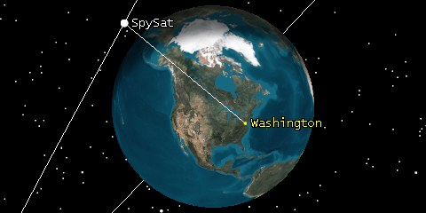
3D View: Access from SpySat to Washington
- Can you spot any unexpected accesses?
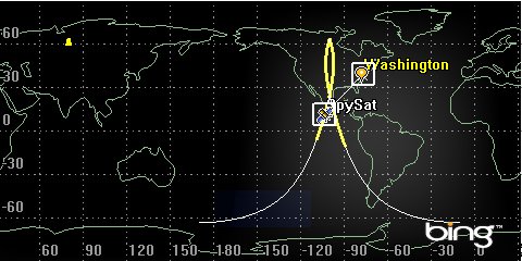
2D View: Access from SpySat to Washington
Report Access Times
Well, access has been calculated, and you can even see that access occurs in the 2D and 3D Graphics windows, but that doesn’t tell you what you need to know. You need to know exactly WHEN access occurs. Data providers can return information about when AND where accesses occur.
- Select the Access tool () to bring it to the front.
- Click the Access... button in the Reports area.
- Take a look at the access report, and answer the following questions:
- How many periods of access are there?
STK will generate and display an access report. The access report lists the start and stop time for each instance that SpySat can “see” Washington.
Start and Stop Times and Step
Using the Start and Stop times in the report header, you can limit the data to a selected portion of the analysis period. The default period for the report is the analysis period. You can also adjust the step to report data in coarser (increase the step) or finer (decrease) increments.
Report Units
Take a look at the first access.
- When does the first access occur?
- What is the duration of the first access?
That’s a lot of seconds. It really doesn’t seem to make sense to report this length of time in seconds, does it? What you’d like to know, is how many hours that is. Can you figure how each duration translates to hours? You don’t need to.
- Select the access report to bring it to the front.
- Click the Report Units button (
 ) at the top of the report.
 - When the Units dialog appears, select Time in the Dimensions list. You will see that the default time unit is set to Seconds (sec).
- Select Hours (hr) from the New Unit Value list.
- Click OK to save the change and dismiss the Units window.
- Return to the access report.
- For how many hours in one twenty-four hour period could you spy on Washington, D.C. from a satellite in a Molniya orbit?
- When you finish, close the access report.
Look at the duration values. They’ve all been converted to hours.
Now, you can answer the question that you set out to solve.
Where Is SpySat When It “Sees” DC?
The access report that you created assures you that SpySat can indeed “see” Washington, and even tells us WHEN SpySat can “see” Washington; but suppose, for instance, you are operating some sort of collection sensor attached to SpySat and you want to know where to point the sensor during access. You’d need to know WHERE SpySat is with respect to Washington when access occurs. Access data can also give you this information.
- Select the Access tool () to bring it to the front.
- Click the AER... button in the Reports area.
- Use the AER report to answer the following questions:
- When is SpySat furthest from/closest to Washington?
- What is the minimum/maximum distance from which SpySat can “see” Washington?
STK will generate and display an AER report. The AER report gives the azimuth, elevation, and range of SpySat, relative to Washington, during each period of access.
Where Is SpySat When DC “Sees” Him?
Turn things around. Suppose you’re in Washington, and you want to know where you can look to “see” SpySat. In this case, you would need to calculate access FROM Washington TO SpySat.
- Select the Access tool () to bring it to the front.
- Click the Select Object... button.
- Select Washington ().
- Click OK.
- Select SpySat () in the Associated Objects list.
- Click the AER... button in the Reports area.
- Use the two AER reports to answer the following questions:
- Is the distance between Washington and SpySat different from Washington’s perspective?
- Would you be able to answer your original question if you had calculated data FROM Washington TO SpySat? How can you tell?
- Close any open reports.
- Close the Access Tool ().
When You Finish
- Save () your work.
- Close the scenario ().
- Leave STK () open.