Create the System Definition Diagram for the Race
Overview
To execute a simulation with Behavior Execution Engine, you need to have a model with a case to target. It is a good practice to design one, so that we can create a use case with actors and a subject.
Prerequisites
| Prerequisite | Description |
|---|---|
| Behavior Execution Engine Installation | You must have installed Behavior Execution Engine. |
| Recommended Reading | Before completing this section, you may want to read the following help topics: |
Instructions for Creating a New Project
- Open the System Architecture Modeler web interface.
- Create a new project by selecting a Blank Project as the Creation method.
- Ensure SysML v2 is selected as the type.
- Give it a useful name such as
TortoiseVsHare Part 1and click .
Instructions
Creating the System Definition Diagram
The first thing to do is to create the structural representation with the part definitions necessary to represent the “system”, which consists of the racers and the race. In this case, you have two primary elements: the race itself and a racer who will participate in the race.
- Create a new General Diagram and give it the name
System Definition. - Create a Part Definition and name it
Race. - Create another Part Definition and name it
Racer.
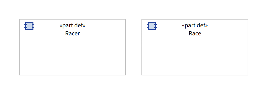
Structure Diagram showing Race and Racer part definitions
Creating the different racers
Since you know both the tortoise and the hare are going to be racers, you can create part definitions for them that are specializations of the Racer part definition. This will enable you to inherit features from the base definition but provide differing behavioral models for each of them.
- Create a Part Definition and name it
Hare. - Draw a Specialization Arrow from the
Harepart definition to theRacerpart definition so thatHarespecializes (inherits from)Racer. - Repeat this process for the
Tortoise.
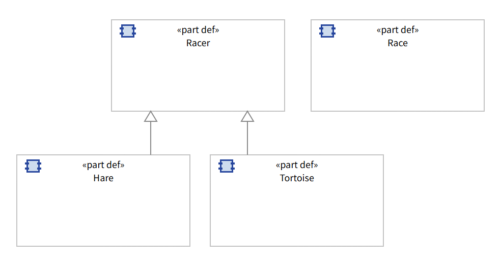
Specializations of the Racer part definition
Importing common libraries for execution
There are a few standard libraries that are useful for execution. Over the course of this tutorial, we will be using four of them. For specifying durations of time, we are going to use the “DurationValue”, “LengthValue”, and “SpeedValue” types from “ISQBase”. The “ScalarValues” package gives us the “Boolean” and “String” types. We will be using the “SI” package to write units in our expressions. Finally, we will be using the “Time” library for specifying specific “TimeInstants”. Behavior Execution Engine only supports TimeInstantValues in the form of attributes typed by “Iso8601DateTime”.
- Right click on the root package in the model tree explorer.
- Select Import library.
- Expand Standard libraries, select the ISQBase package, and press the button.
- Repeat the above steps for ScalarValues, SI, and Time libraries.
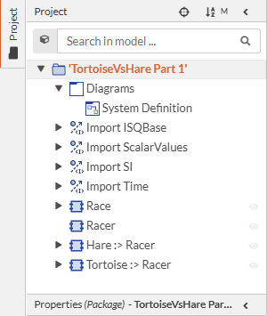
Libraries Imported into the model tree explorer
Adding properties to the Race and Racer
With the basic model defined, you can begin to explore what types of information you need to adequately describe the individual elements so Behavior Execution Engine can simulate them. In the case of the race, you can easily imagine there are a few attributes that you need to describe it, such as the start time and distance for the runners to cover. For the racers, you will need them to start and stop racing. You will need attributes to describe how fast they can run and how far they have run at any given time during the simulation. Since the racers will need to “know” about each other, you also need to describe the relationship between the racers and the race.
-
For the
Racerpart definition do the following:- Create an Attribute with the name
distanceCovered, set the definition to LengthValue, and give it an initial value of0 [m]. - Create an Attribute with the name
raceFinished, set the definition to Boolean, and give it an initial value offalse.
- Create an Attribute with the name
-
For the
Racerpart definition do the following:- Create an Attribute with the name
distanceCovered, set the definition to LengthValue, and give it an initial value of0 [m]. -
Create an Attribute with the name
raceFinished, set the definition to Boolean, and give it an initial value offalse.Note - "isInitial" in SysML indicates that the value of an attribute is valid at the start of the owning Occurrence (such as a Part, Item, Action, or State), but that the value can change over the life of that Occurrence. If "isInitial" is false, this indicates that the attribute is bound to have that value for the entire life of the Occurrence.
- Create an Attribute with the name
topSpeedand set the definition to SpeedValue. - Create an Attribute with the name
nameand set the definition to String. - Create an Action and name it
startRacing. - Create an Action and name it
stopRacing. - Create a State and name it
existing.
- Create an Attribute with the name
-
Create a Part with the name
race.- Draw a Definition Arrow from the
Racepart to theRacepart definition so that race is defined by (inherits from)Race. - Draw a Referential Containment Arrow from the
Racerpart definition to theRacepart so thatRacercan referenceRace.
- Draw a Definition Arrow from the
-
For the
Harepart definition do the following:- Expand the
Harepart definition in the model tree explorer. - Redefine the inherited
^existingstate. - Redefine the inherited
^nameattribute and give it a bound value ofhare.
- Expand the
-
For the
Tortoisepart definition do the following:- Expand the
Tortoisepart definition in the model tree explorer. - Redefine the inherited
^existingstate. - Redefine the inherited
^nameattribute and give it a bound value oftortoise.
- Expand the
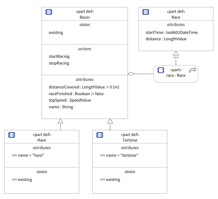
Diagram of the initial model
Configuring part usages as non-composite "references" to other parts is a way to have access to another part or actor without that part being considered physically inside the owning usage. When creating and ultimately destroying parts, destroying a part will also destroy any owned composite parts. So, consider whether each part is a physical sub-component of the owner. If not, it should probably not be a "composite" part and instead be a reference.
If you your diagram is missing any information that exists in the model but is not visible, you can right click on an element and click the or buttons.
Next Section >