Creating Instances in Instance Specification Diagrams
Overview
After defining your blocks, you need to create instance specifications for them so that you can use them in your simulation. Instance specifications enable you to set the initial property values for the blocks in your simulation. In this section, you will create an instance specification diagram containing instance specifications for each of the blocks in your Instance Specification Definition Diagram.
This section covers the following concept:
- Instance specifications and instance specification diagrams
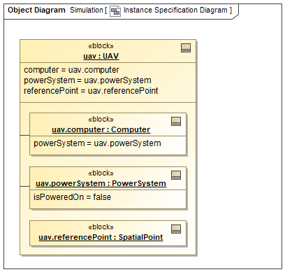
Figure A1: An instance specification diagram
Prerequisites
| Prerequisite | Description |
|---|---|
| Behavior Execution Engine Installation | You must have installed Behavior Execution Engine. |
| Tutorial Project | You must start this section with the Behavior Execution Engine simulation project from the previous section. If you did not complete the previous section, you can use the following project from the Behavior Execution Engine installation: \documentation\tutorialFiles\01\PropertiesAndOperations.mdzip |
| Recommended Reading |
Before completing this section, you may want to read the following help topic:
|
Instructions
Create an instance specification diagram
To simulate behaviors in Behavior Execution Engine, you need to create instances for the blocks that own those behaviors. You can easily accomplish this by creating an instance specification diagram.
- Open the project from the previous section.
-
In the Containment Tree,
right-click the Structure >
UAVblock and select Tools > Create Instance.... -
In the 1. Select parts page,
expand the
computerproperty, clear thepowerSystemproperty check box inside thecomputerproperty to avoid creating an extraPowerSysteminstance specification, and click .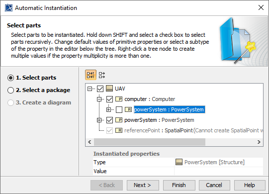
Figure B1: Selecting instance specifications
- In the 2. Select a package page, select the Simulation package and click .
- In the 3. Create a diagram page, select both the Create a new diagram and Create link between instances check boxes.
- In the diagram type box, select Object Diagram.
- In the owner for diagram box, select the Simulation package.
-
In the diagram name text box,
enter
Instance Specification Diagram, and then click .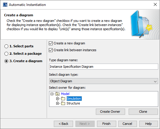
Figure B2: Creating an instance specification diagram
You could drag the simulation instance specification onto this diagram if you want.
However, since it is used to execute the simulation rather than being a component of the system being simulated,
it more logically belongs on a simulation configuration diagram,
as mentioned in the Simulation Configuration section.
Specify the computer's power system
Since the Computer block only references the PowerSystem block rather
than owning it,
a Computer instance specification could reference any PowerSystem
instance specification.
When creating the instance specification diagram earlier,
you avoided creating an extra PowerSystem instance specification for the uav.computer
instance specification,
so you should specify that it uses the UAV's power system.
-
In the Instance Specification Diagram,
double-click the
uav.computerinstance specification to open its specification window and select Slots from the left pane of the window. -
In the center pane,
select the
powerSystemslot and click . -
Select the Simulation >
uav.powerSysteminstance specification; then click and then . -
(Optional)
In the Instance Specification Diagram,
drag the
uav.referencePointinstance specification into theuavinstance specification. TheUAVblock's inheritedreferencePointproperty could theoretically be independent, but in this tutorial it represents the UAV's center of mass.Figure B3: The system instance specifications
- (Optional) You may also want to drag the uav instance onto the Simulation Definition Diagram for reference there as well. To do that, drag the element from the Containment Tree onto the Simulation Definition Diagram.
- Save your work before continuing.
Next Section >