Simulating Simultaneous Behaviors with Composite States
Overview
In order to simulate simultaneous behaviors within a state machine, you must use a composite state. A composite state is a single state divided into orthogonal regions, each of which contains substates that represent that region's behavior. The substates are only mutually exclusive within each region, not across regions, so that all of the regions can execute at the same time. In this section, you will use a composite state to simulate the computer interacting simultaneously with both the power system and the flight controller.
This section covers the following concepts:
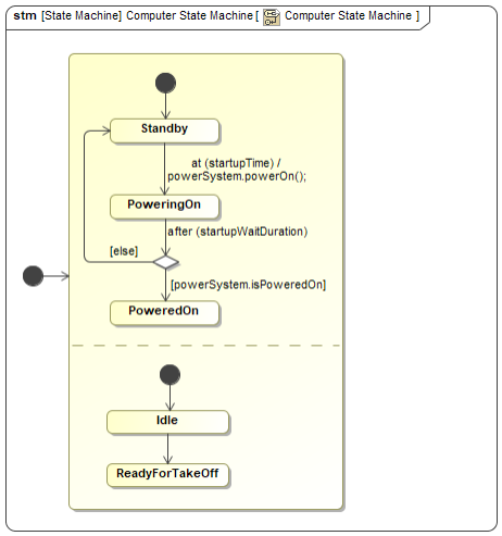
Figure A1: A composite state
Prerequisites
| Prerequisite | Description |
|---|---|
| Moxie Installation | You must have installed Moxie. |
| Tutorial Project | You must start this section with the Moxie simulation project from the previous section. If you did not complete the previous section, you can use the following project from the Moxie installation: \documentation\tutorialFiles\02\TimeEvents.mdzip |
| Recommended Reading | Before completing this section, you may want to read the following help topic: |
Instructions
Create a block for the flight controller
For the computer to instruct the flight controller to arm its motors, you will need to create a block, instance specification, and state machine to represent the flight controller and its properties and behavior.
- Open the project from the previous section.
-
In the System Definition (the BDD),
select the
Thingblock, click the downward-pointing Generalization button ( ) on the context toolbar,
and then click anywhere on the canvas to add a new block.
) on the context toolbar,
and then click anywhere on the canvas to add a new block.
-
Select the new block on the diagram
and enter
FlightControlleras its name. -
Select the
UAVblock, click the Directed Composition button ( ) on the context toolbar,
and then click the
) on the context toolbar,
and then click the FlightControllerblock. -
In the toolbar to the left of the BDD canvas,
select Directed Association,
click the
Computerblock, and then click theFlightControllerblock.
Create an instance specification for the flight controller
-
Right-click the
FlightControllerblock and select Tools > Create Instance.... - In the 1. Select parts page, click .
- In the 2. Select a package page, select the Simulation package and click .
- In the 3. Create a diagram page, clear the Create a new diagram checkbox and click .
-
In the Containment Tree,
rename the new Simulation >
flightControllerinstance specification touav.flightController. - Open the Instance Specification Diagram.
-
Drag the Simulation >
uav.flightControllerinstance specification from the Containment Tree into theuavinstance specification on the diagram and click . -
(Optional)
Click the Link button (
 ) on the context toolbar next to the
uav.flightControllerinstance specification. Then click on theuavinstance specification to add the link. Click on both pages of the dialog window. -
Double-click the
uav.computerinstance specification and select Slots from the left pane of the specification window. -
In the center pane,
select the
flightControllerslot and click . -
Select the Simulation >
uav.flightControllerinstance specification; then click and then .
Create a state machine for the flight controller
-
In the Containment Tree,
right-click the Structure >
FlightControllerblock and select Create Diagram (or press ). -
Select SysML State Machine Diagram
and enter
FlightController State Machineas its name. You may need to click the button in the lower left of the dialog in order to find SysML State Machine Diagram. -
Select the state on the diagram
and enter
Idleas its name. -
Click the Transition button (
 ) on the context toolbar,
click anywhere on the canvas to add a new state,
and then enter
) on the context toolbar,
click anywhere on the canvas to add a new state,
and then enter ReadyForTakeoffas its name. - Open the Simulation Dashboard.
-
Drag the Structure >
FlightController> FlightController State Machine > FlightController State Machine diagram onto the dashboard and click the Show Diagram Overview Content button ( ) to display the state machine.
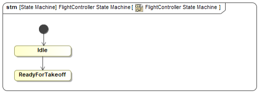
Figure B1: The flight controller state machine
Add a composite state to the computer state machine
Since you need to create additional behavior that will run at the same time as the computer's existing behavior, you need to nest the states describing both behaviors inside a composite superstate.
- In the Computer State Machine diagram, select Composite State from the toolbar to the left of the canvas and then click anywhere on the canvas to add a composite state.
- Select the rest of the state machine elements and drag them into the body of the composite state.
-
Select the composite state
and click the Create Region button (
 ) on the upper-right corner of the state.
- In the toolbar to the left of the state machine canvas, select Initial and click in the new region of the composite state to add an initial pseudostate.
-
Click the Transition button () on the context toolbar,
right-click in the region and select State,
and then enter
Idleas its name. -
Click the Transition button () on the context toolbar again,
right-click in the region and select State,
and then enter
ReadyForTakeoffas its name. - In the toolbar to the left of the state machine canvas, select Initial and click anywhere on the canvas to add an initial pseudostate.
-
Click the Transition button () on the context toolbar.
Then click the composite state.
-
Run (
 ) the simulation
and observe that both regions of the composite state execute simultaneously.
) the simulation
and observe that both regions of the composite state execute simultaneously.
Figure A1: The computer composite state
- Save your work before continuing.
Though both regions execute simultaneously, they do not yet interact with the flight controller state machine. You will add this interaction in the next section using a call event.
Next Section >