Examining the Mission Components
Overview
Modeling a mission in SysML is essentially the same as modeling a system. You define the blocks, instance specifications, and state machines for the actors in the mission, and then you can use Moxie to execute the simulation. The difference is that mission simulations often require modeling high-fidelity, time-dynamic, physics-based aspects of the systems and environment. With Moxie, you can integrate analysis tools like Systems Tool Kit (STK) into your simulation and let them handle those physics complexities implicitly, without needing to explicitly build the physics into your SysML. In this section, you will examine a pre-made STK scenario of a UAV flying a mission, as well as a SysML model based on the previous tutorials but updated to include the important elements of the mission.
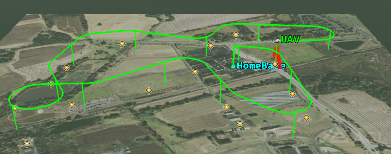
Figure A1: The UAV's mission
Prerequisites
| Prerequisite | Description |
|---|---|
| Moxie Installation | You must have installed Moxie. |
| STK Installation | You may want to have installed 12 . |
| Tutorial Project |
The project files used in this tutorial are based on the project from the previous tutorial,
but contain additional content, so you may want to refer to them during the discussion.
You can find the following project files in the Moxie installation:
|
| Recommended Reading | Before completing this section, you may want to review the previous tutorials, which form the basis for the discussion here. |
Discussion
The mission you will be simulating in this tutorial is a flight test of a camera system on the UAV, evaluating the ability of the camera to detect and then focus on objects of interest and take a photo before the UAV flies too far away. The UAV flies a fixed path and the objects are stationary, so the main variables are the field of view of the camera when searching and the time it takes to calibrate when focusing on an object before taking a photo. The constraints are that the camera system can neither draw too much power nor weigh too much, otherwise the UAV will be unable to fly.
STK scenario
The STK scenario for this mission contains the basic physical objects and environment involved: the UAV and its attached camera, its home base, its pre-programmed flight path, and the objects of interest that it will try to take photos of. The UAV's flight is specified by ephemeris and attitude files that are included in the UAVMission.vdf file, so you do not need any advanced capabilities like STK Aviator to be able to run the scenario.
If you run the scenario, you will see the UAV fly past all of the objects. You can even generate reports to see which objects the UAV is able to detect with the current camera settings. With just STK, the UAV's behavior is always set before running the scenario. Moxie, however, allows you to integrate with the SysML model to simulate the behavior of the UAV reacting to its environment during the simulation by focusing its camera on the objects it detects and taking photos of them.
Figure B1: The STK scenario
SysML model
STK fully handles the elements of the physical environment that do not have their own behavior or need to change during the simulation, namely the flight path and the objects of interest. So, the SysML model only needs to include the UAV, home base, and camera from the scenario. Accordingly, the main features that have been added to the SysML model since the previous tutorial are:
- UAV and ground station state machines to model the coordination of the mission
- A sensor payload state machine to model the reactive behavior of the UAV's camera during the mission
- Improvements to the power system and computer state machines to model the power draw of the subsystems
If you examine the SysML project file, you will notice some additional properties and operations.
Most support the new behavior that was added, while a few are for the delegates to integrate with STK.
You may also notice that the SysML model is a bit more abstract than the STK scenario,
using GroundStation instead of HomeBase,
and SensorPayload instead of Camera.
These kinds of discrepancies can easily occur if one team member creates the SysML model while another creates the STK scenario.
Fortunately, you can easily resolve them when connecting the two through the delegates.
If you run the simulation at this point, you will notice that the sensor payload never actually takes any photos, because it never detects any objects. This detection of objects requires knowledge of the physical environment, which the SysML model does not have. So in this tutorial, you will create delegates that add this capability and others by integrating with STK. If you previously installed any of the UAV mission delegates from this tutorial or from the sample fully-completed tutorial included in the Moxie installation, then remove them from your delegate module home directory before running the simulation.
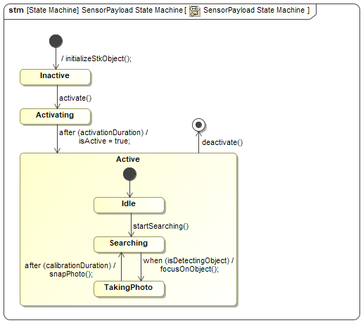
Figure B2: The sensor payload state machine
Next Section >