Modulators
STK Modulators can be separated into five general categories: Common Analytical Modulators, Jammer/Interference Modulators, Coded Modulators, External File Modulators, and Script Plugin Modulator. STK Communications allows you to select from a number of built-in modulators or incorporate user defined modulators, including those which model coding or are dynamic in behavior.
Common Analytical Modulators
These modulators are built into STK and can compute their power spectral density (PSD) characteristics analytically. All these modulators share the following parameters:
Name. The name of the selected modulator.
Use Signal PSD. Models the signal using a power spectral density. This is used to determine the Bandwidth Overlap Factor. If this option is not selected, the PSD is modeled as a flat spectrum with unity magnitude across the transmitter’s bandwidth. See Signal Bandwidth for an explanation of the bandwidth for which the signal is defined.
Signal Bandwidth. For a transmitter, you can specify the transmitted RF bandwidth or you can select Auto Scale. When Auto Scale is enabled, the transmitter adjusts its transmitting bandwidth on the basis of its data rate and the modulation’s spectral efficiency (see Modulation Bandwidth Ratios).
When bandwidth auto-scaling is enabled, the bandwidth of the transmitted signal is fifteen times the Chip Rate. Thus, the bandwidth of the transmitted signal is represented by the following equation:
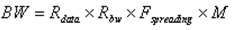
where
Rdata is the transmitter’s data rate.
Rbw is the bandwidth ratio of the modulation (see Modulation Bandwidth Ratios)
Fspreading is the spreading factor.
M is number of nulls to extend the PSD (default is 15)
If auto-scaling is disabled, you can specify the bandwidth as symmetric (centered around the carrier frequency) or asymmetric. If Symmetric is not selected, you can specify the upper and lower bandwidth limits for the transmitter. These values are specified relative to the carrier frequency (where the carrier frequency is defined as 0 Hz). Therefore, the upper bandwidth limit must be a positive value and the lower bandwidth limit must be a negative value.
CDMA Spreading. You can model CDMA (Code Division Multiple Access) gain by selecting Use and entering the desired chips/bit value. CDMA gain improves the C/N carrier-to-noise ratio by a factor equal to the CDMA gain.
The following is a list of Common Analytical Modulators available with STK:
- BPSK - Bi-phase shift keying
- 8PSK - Phase shift keying with 8 constellation points.
- 16PSK - Phase shift keying with 16 constellation points.
- QPSK - Quadrature phase shift keying
- OQPSK - Offset QPSK
- MSK - Minimum shift keying
- FSK - Frequency shift keying
- DPSK - Differential phase shift keying
- NFSK - Non-coherent frequency shift keying
- QAM16 - Quadrature Amplitude Modulation with 16 constellation points
- QAM64 - Quadrature Amplitude Modulation with 64 constellation points
- QAM128 – Quadrature Amplitude Modulation with 128 constellation points
- QAM256 – Quadrature Amplitude Modulation with 256 constellation points
- QAM1024 – Quadrature Amplitude Modulation with 1024 constellation points
- BOC – Binary-Offset-Carrier
The BOC modulation type requires you to enter a subcarrier frequency. Two times the subcarrier frequency divided by the chip rate must be an integer value.
Modulation Bandwidth Ratios
The modulator bandwidth ratio is the required bandwidth in Hz per bit per second, written as Hz/bps. The ratios used in STK represent the null-to-null bandwidths of the main lobe of the power spectrum. For details on how the transmitter’s bandwidth factors into the link budget calculation, see Bandwidth Overlap Factor.
The table below shows the modulation’s bandwidth ratio (spectral efficiency) for each modulation type:
| Modulation Type | Bits / Symbol | Bandwidth Ratio (Hz/bps) |
|---|---|---|
| BPSK | 1 | 2.0 |
| 8PSK | 3 | 0.666666… |
| 16PSK | 4 | 0.5 |
| QPSK | 2 | 1.0 |
| OQPSK | 2 | 1.0 |
| MSK | 1 | 1.5 |
| FSK | 1 | 2.0 |
| DPSK | 1 | 2.0 |
| NFSK | 1 | 2.0 |
| QAM16 | 4 | 0.5 |
| QAM64 | 6 | 0.333333… |
| QAM128 | 7 | 0.285714… |
| QAM256 | 8 | 0.25 |
| QAM1024 | 10 | 0.2 |
| BOC | 1 | 2.0 |
Jammer/Interference Modulators
The Jammer/Interference Modulators can be broken down into two sub-categories, Analytical Jammer/Interference Modulators and Radar Jammer/Interference Modulators.
Analytical Jammer/Interference Modulators
Three analytical modulators have been added specifically for modeling wideband and narrowband jammers.
- WidebandGaussian
- NarrowbandUniform
- WidebandUniform
If you choose any of these modulators for a transmitter being used in a link budget calculation, a BER of zero will be determined regardless of the link Eb/No computed.
When the WidebandGaussian modulator is selected, the bandwidth entered represents the +/- 3 sigma value for the Gaussian distribution. When either the narrowband or wideband uniform modulators are selected, the bandwidth entered represents the spectral limits of the modeled modulated signal. Also, you have the option of making the jammer’s bandwidth asymmetrical by clearing Symmetric Bandwidth and entering an upper bandwidth limit (+3 sigma for Gaussian) value different from the lower bandwidth limit (-3 sigma for Gaussian) value.
Radar Jammer/Interference Modulators
Modulators added specifically for modeling radar jamming/interference include:
- Pulsed Signal
Pulse Signal modulator will modulate the RF carrier with a sequence of digital pulses. This modulator may be used to model a pulsed radar signal acting as a jamming/interfering source in a Comm System interference analysis. You can control the pulse period( 1 / pulse repetition frequency (PRF)), pulse width, and the number of pulses in the signal sequence.
The following parameters define this modulator:
Pulse Period. Total duration of each pulse. All the pulses in the sequence are considered to have the same pulse period or PRF.
Pulse Width. Duration of time when the RF pulse is enabled. The pulse width must be less than the pulse period.
If you need to set a pulse width value that is larger than the default pulse period value, set the new pulse period value before the pulse width. STK compares the pulse width with the pulse period and may not set the value if the existing pulse period value is less than the pulse width.
Number of Pulses. Number of pulses in the modulating pulse sequence.
The spectrum of the pulsed modulator is a sequence of sinc pulses in the frequency domain. Each spectrum pulse has a ![]() spectral shape. The peak amplitude of the sequence of spectral pulses also follows a sinc pattern curve.
spectral shape. The peak amplitude of the sequence of spectral pulses also follows a sinc pattern curve.
Coded Modulators
STK Communications makes available several additional coded modulator files, which are located in <STK install folder>\STKData\Comm\SrcModFiles. If you add your own custom or third-party modulator files to the SrcModFiles folder with a .mod file name extension, their names will appear in the list as well (see External Modulators)
If STK is running when you add the new files to the SrcModFiles subdirectory, you must restart STK in order to have the names of the new files appear as a selection in the Component Browser.
Coded modulators currently available include the following:
Additional Modulation Types
| Modulation Type | Code Rate (unitless) |
Modulation Efficiency
(Hz/bps) |
Encoded Bandwidth Ratio (Hz/bps) |
|---|---|---|---|
|
BPSK-BCH-127-64 |
0.503937007874 |
2
|
3.96875 |
|
BPSK-BCH-255-123 |
0.482352941176 |
2
|
4.1463414634146341 |
|
BPSK-BCH-511-259 |
0.506849315068 |
2
|
3.945945945945945946 |
|
BPSK-BCH-63-30 |
0.476190476190 |
2
|
4.2 |
|
BPSK-Conv-2-1-6 |
0.5 |
2
|
4.0 |
|
BPSK-Conv-2-1-8 |
0.5 |
2
|
4.0 |
|
BPSK-Conv-3-1-6 |
0.333333333333 |
2
|
6.0 |
|
BPSK-Conv-3-2-6 |
0.666666666667 |
2
|
3.0 |
|
BPSK-Conv-3-2-8 |
0.666666666667 |
2
|
3.0 |
|
BPSK-Conv-4-3-6 |
0.75 |
2
|
2.6666666666666667 |
|
BPSK-Conv-4-3-8 |
0.75 |
2
|
2.6666666666666667 |
|
NFSK-BCH-127-92 |
0.724409448819 |
2
|
2.7608695652173913043 |
|
NFSK-BCH-255-191 |
0.749019607843 |
2
|
2.6701570680628272 |
|
NFSK-BCH-511-385 |
0.753424657534 |
2
|
2.6545454545454545 |
|
NFSK-BCH-63-45 |
0.714285714286 |
2
|
2.8 |
External Modulators
The external modulator file allows you to specify a custom modulation spectral efficiency, code rate, and/or power spectral density. Common uses of this is to incorporate encoding and/or a specialized shape for the power spectral density. The external modulator file can provide a series of points describing the power spectral density. BER performance is a function of Eb/No. The external file is comprised of special key words and associated user values.
For more information, see External Modulator File.
Script Plugin Modulators
Script Plugin modulators are user defined scripts that allow you to define the modulator including its behavior. Script languages can be VB Script, Perl, or MATLAB. Unlike the External file modulators that are static in nature, these can be time-dynamic, if so desired.
The plugin script is not automatically reloaded after you make changes to it. To reload the script, click Reload.
For a description of the script’s input and output parameters, see Modulator's Script Arguments.
 Visit AGI.com