Cosecant Squared Pattern Antennas
The cosecant squared beam type is defined by the following equation:
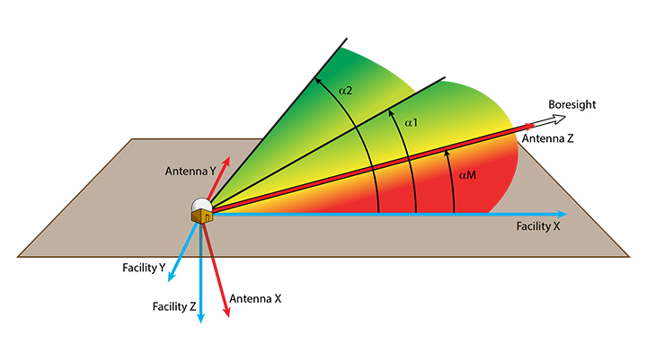
The following illustration depicts a typical use case of a cosecant squared antenna pattern applied to a ground-based air search radar. It also illustrates that:
- The angle
 m is the upward tilt angle of the beam relative to the horizontal, generally about half a beamwidth.
 - In this particular example, the elevation angle is set to the same value as alpha_M.
See Raemer, Harold R., Radar Systems Principles, Boca Raton: CRC Press (1997), pp. 359-362.
This antenna uses a polar coordinate system.
You can specify the following parameters:
| Parameter | Description |
|---|---|
| Alpha 1 Angle | The angle 1 in the above equation and illustration. |
| Alpha 2 Angle | The angle 2 in the above equation and illustration. |
| Azimuth Beamwidth | The full width of the beam in the x-y plane of the beam coordinate system. |
| Design Frequency |
The frequency of the antenna. For an embedded antenna on a receiver, transmitter or radar, this value corresponds to the Frequency entered on the Model Specs tab for the transmitter or receiver and the Transmitter Specs tab for the Radar. For an antenna linked to a receiver, transmitter, or radar, the Antenna Design Frequency value gets overridden by the Frequency value set on the Model Specs tab for the transmitter or receiver, and the on the Transmitter Specs tab for the Radar. However, when computing the antenna's gain matrix (or a link budget, etc.) from one of the objects linking to the antenna, that other object's frequency settings override the antenna's Design Frequency setting. |
| Alpha M Angle | The angle m in the above equation and illustration. |
| Main-lobe Gain (dB) | The main lobe gain of the antenna pattern. |
| Side-lobe Gain (dB) | The side lobe gain of the antenna pattern. Absolute; not relative to the Main-lobe gain. |
| Efficiency | The efficiency of the antenna (a value between 0 and 100 percent). |
 Visit AGI.com