Parabolic Antenna
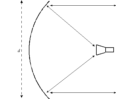
An analytical model of a uniformly illuminated parabolic antenna, shown below.
This antenna uses a polar coordinate system.
| Field | Description |
|---|---|
| Design Frequency |
The frequency of the antenna. For an embedded antenna on a receiver, transmitter or radar, this value corresponds to the Frequency entered on the Model Specs tab for the transmitter or receiver and the Transmitter Specs tab for the Radar. For an antenna linked to a receiver, transmitter, or radar, the Antenna Design Frequency value gets overridden by the Frequency value set on the Model Specs tab for the transmitter or receiver, and the on the Transmitter Specs tab for the Radar. However, when computing the antenna's gain matrix (or a link budget, etc.) from one of the objects linking to the antenna, that other object's frequency settings override the antenna's Design Frequency setting. |
| Beamwidth | The beamwidth of the antenna gain pattern. Valid if Use Beamwidth is selected. The diameter and gain are automatically calculated on the basis of this value and the frequency. |
| Diameter | Diameter of the dish. Valid if Use Diameter is selected. The beamwidth and gain are automatically calculated on the basis of this value and the frequency. |
| Main-Lobe Gain | Select the Use Max Gain option and enter the value in dB. The diameter (or dimension) and beamwidth are automatically calculated on the basis of this value and the frequency. |
| Efficiency | Specifies the efficiency factor of the dish, varying from 0 to 100 percent. Since no antenna is perfect, the efficiency factor allows you to specify the degradation in performance. Typical values fall in the range of 50 to 75 percent. |
| Back-lobe Gain |
Back-lobe gain can be used two different ways:
|
 Visit AGI.com