Covariance
Setup
Error Covariance Matrix
The Covariance page allows you to input the initial state error covariance matrix. Because the matrix is symmetric, only the lower triangle needs to be entered. The matrix naturally decomposes as:
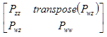
where Pzz is the 6x6 symmetric position/velocity covariance, Pwz is an nx6 matrix representing the cross-correlation between consider parameters and the position and velocity covariance, and Pww represents the consider parameter covariance matrix (which is also symmetric). Here n is the number of consider parameters being used.
Cartesian covariance units are m^2, m^2/s, m^2/s^2.
The following additional parameters can be set:
Error Covariance Parameters
Frenet Coordinate Frame
To facilitate understanding of the frames, the following directions are defined:
| Symbol | Name | Description |
|---|---|---|
|
R
|
Radial | Along line from center of Earth through satellite position |
|
I
|
In-track | Normal to radial direction, towards inertial velocity |
|
C
|
Cross-track | Along the orbit angular momentum vector (R x I) |
|
T
|
Tangential | Along the inertial velocity direction |
|
N
|
Normal | Normal to tangential direction, towards radial direction |
The Frenet Coordinate frame is an axes definition defined as (N)(T)(C). When Frenet is selected the local frame of reference for the Yaw Pitch Roll (YPR) is (T)(-C)(-N).
Rotations are performed in the sequence with the nominal thrust direction, specified via a (0,0,0) rotation, being along the X axis of the local frame. The nominal thrust direction is in the (T) direction for the Frenet frame.
Consider Parameters
You can choose which, if any, consider parameters to include when propagating covariance. Simply check the Use checkbox in the grid to turn on a consider parameter. The Value column corresponds to the self-covariance of that parameter (i.e. the value that appears as the diagonal element of Pww); the other columns are for entering cross-correlations between that parameter and position/velocity covariance. While the Value column must be non-negative, the others columns can be positive or negative. However, the overall state error covariance matrix must be positive definite; thus, the cross correlations cannot be too large compared to the diagonal elements of Pzz. Usually, this cross correlation is ignored (i.e. values are set to zero for the position/velocity cross-correlation).
All Varieties of HPOP make the following consider parameters available:
- Drag -- the consider parameter is D, where D = Cd * DragArea/Mass
- SRP -- the consider parameter is K, where K = Cr * SRPArea/Mass
Consider Cross Relation
In most cases, users will not want to model cross-correlation among the consider parameters themselves, i.e. Pww is modeled as a diagonal matrix. However, the user can choose to model cross-correlation effects as well using the third grid. Simply add rows in that grid to represent each non-zero cross-correlation. For each row, choose the two consider parameters (double-click in the Row or Column cells to choose the correct parameter) that have the correlation, and enter the cross-correlation.
Background
HPOP is capable of propagating the state error covariance matrix as it is propagating ephemeris. The state error covariance matrix represents the uncertainty in the vehicle's position and velocity. The vehicle's position covariance submatrix can then be reported and graphed and can be displayed in the 3D Graphics window over time.
State error covariance growth is usually dominated by the initial position and velocity covariance, which is typically generated by orbit determination software. Any errors between the estimated state and the actual state tend to grow over time, especially in the along-velocity direction. This is a direct effect of the dominant two-body force, since the period of the orbital motion is on its initial state. Eccentric orbits also show a oscillation in uncertainty superposing the growth trend, whose amplitude is larger for larger eccentricity. Uncertainty increases near perigee where the speed of the vehicle is largest in its orbital cycle; uncertainty will actually decrease near apogee where the speed is the smallest
A second contributor to state error covariance growth is force model mis-modeling, i.e. the force model environment modeled by the software (chosen by the user to best represent the force environment) nevertheless does not precisely model the actual forces experienced by the vehicle. In orbit determination software that uses Kalman or related filters, force model mis-modeling contributes to covariance growth through process noise models which aim to characterize the uncertainty of the modeling itself. Because HPOP does not have all the data needed to do this sophisticated analysis, it uses a simpler scheme to account for some force model mis-modeling called "consider analysis."
A consider analysis adds contributions of force model mis-modeling to the state error covariance propagation by treating constant parameters in the force model as being instead uncertain themselves. The uncertainty in the parameter value leads to uncertainty in the force evaluation, which then contributes to the state error covariance.
 Visit AGI.com