Using STK Connect to Plan a Predator Mission
STK Professional.
The results of the tutorial may vary depending on the user settings and data enabled (online operations, terrain server, dynamic Earth data, etc.). It is acceptable to have different results.
Watch the following video, then follow the steps below incorporating the systems and missions you work on (sample inputs provided).Problem Statement
Use STK to mission plan an RQ-1 Predator training mission in the vicinity of Mount St. Helens. The training will be taking place on a continuous basis using the same flight route for the Predator. The only things that will change are ground target locations that the Predator will be photographing. In order to simplify the process of creating new STK scenarios when mission planning, create a Microsoft Excel spreadsheet that will only require mission planners to enter new target geodetic coordinates for each mission.
Solution
Build an Excel spreadsheet that allows mission planners to take the data out of each cell, format the data and then concatenate the data into a Connect command that can quickly be used in STK to build a scenario.
Create an Excel Workbook.
Begin by creating an Excel Workbook which you'll use to populate the STK scenario. This workbook could be saved and used over and over again whenever mission planners are moving target locations.
- Open Microsoft Excel
- Click the File menu and select Save As.
- Save the spreadsheet as a Excel Workbook (*.xlsx) named TargetGenerator where you can find it later.
- Begin by naming the columns in the workbook by copying and pasting the below information into the workbook.
- Click on cell A2 and type Target1.
- Click cell A2. On the lower right corner, you can see a small black box. Place your cursor on the box and it will turn into a small plus sign. Hold down your left mouse button and drag the box to cell A6. This is a quick way to add the remaining targets.
- Click on cell C2 and type Geodetic.
- Repeat the instructions in step 6 for cells C2 through cell C6.
Whenever you place text in a cell that overflows into adjoining cells, you can use your mouse to resize the columns. To use your mouse, rest the cursor on right side of the column boundary you want to move until it becomes a resize cursor resize (double-headed arrow), and then drag the boundary until the column is the width you want or simply double click.
| Cell | Name |
|---|---|
| A1 | Target ID |
| B1 | New Command |
| C1 | Coordinate Type |
| D1 | Latitude |
| E1 | Longitude |
| F1 | SetPosition Command |
| G1 | VO Model Command |
| H1 | SetHeightAboveGround Command |
| I1 | SetAzElMask Command |
| J1 | SetConstraint Command |
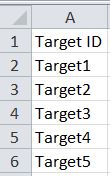
Target ID
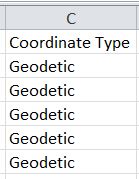
Coordinate Type
Insert Waypoint Coordinates
Prior to creating the scenario, mission planners provide you the coordinates of the targets of which Predator will take pictures during the mission.
- Enter the following coordinates into the workbook by copying and pasting the below information.
- Save your workbook and keep it open.
| Cell | Name |
|---|---|
| D2 | 46.539 |
| D3 | 46.468 |
| D4 | 46.961 |
| D5 | 46.568 |
| D6 | 46.2 |
| E2 | -122.97 |
| E3 | -122.613 |
| E4 | -122.313 |
| E5 | -122.027 |
| E6 | -122.186 |
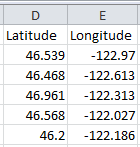
Coordinates
Create a New Scenario
Create a new scenario using the default analysis time period.
- Launch STK (
 ).
). - Create a scenario.
- Name the scenario "Connect."
- Use the default analysis time period.
- When the scenario opens, remove the Timeline View.
- Save (
 ) the scenario.
SAVE OFTEN!
Add Terrain
If you have an Internet connection, you only need to add analytical terrain. Microsoft Bing Maps can be used for imagery. However, imagery is not required.
- Open the Scenario's (
 ) properties (
 ).
). - Browse to the Basic - Terrain page.
- Click Add.
- When the Open pop up window appears, change the file type pull down menu to AGI Terrain File (PDTT).
- Browse to <STK install folder>\Help\stktraining\imagery.
- Select StHelens_Training.pdtt file.
- Click OK.
3D Graphics Window
Since you're using terrain in the 3D Graphics window, a common user preference is to use Label Declutter. It declutters labels away from the central body and towards the viewer, keeping the labels from being obscured by the terrain.
- Bring the 3D Graphics window to the front.
- Right-click on the 3D Graphics window and select Properties ().
- Select the Details page.
- Enable the Label Declutter option.
- Click OK.
RQ-1 Predator
Insert an Aircraft object and use the GreatArc propagator to build your flight route.
- Using the Insert STK Objects tool (
 ), insert an Aircraft (
 ) object using the Insert Default () method.
 - In the Object Browser, rename the Aircraft object "Predator."
- Open Predator's () properties ().
Create Waypoints
If you look at the top of the Basic - Route page, you can see that the Propagator defaults to Great Arc.
- Click the Insert Point button.
- Make the following changes to the waypoint:
- Click the Insert Point button and change waypoint 2's Longitude to -122.9 deg.
- Click the Insert Point button and change waypoint 3's Latitude to 46.1 deg.
- Click the Insert Point button and change waypoint 4's Longitude to -122.5 deg.
- Click the Insert Point button and change waypoint 5's Latitude to 46.9 deg.
- Click the Insert Point button and change waypoint 6's Longitude to -122.1 deg.
- Click the Insert Point button and change waypoint 7's Latitude to 46.1 deg.
- Click the Insert Point button and change waypoint 8's Longitude to -121.5 deg.
- Click Apply.
After entering data into a cell, click the Enter button on your keyboard prior to going to the next cell.
| Option | Value |
|---|---|
| Latitude | 46.9 deg |
| Longitude | -123.5 deg |
| Altitude | 20000 ft |
| Speed | 100 mi/hr |
| Turn Radius | 1.0 km |
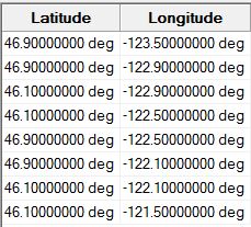
Predator Waypoints
Change Predator's Attitude
To add realism to Predator's flight profile, have Predator roll when turning.
- Select the Basic - Attitude page.
- Change the Basic - Type to Coordinated Turn.
- Click Apply.
A coordinated turn computes the roll (banking) of an aircraft based on a balancing of the forces acting on the aircraft, assuming a zero angle of attack and no slip condition.
Change Predator's Model
To add realism to the scenario, apply a more accurate model to Predator.
- Browse to the 3D Graphics - Model page.
- Click the (
 ) beside the Model File option.
 - Select rq-1a_predator.mdl and click Open.
- Click OK.
- Bring the 3D Graphics window to the front.
- In the Object Browser, right-click on Predator () and select Zoom To.
- Bring the 2D Graphics window to the front.
- Using your mouse pan and zoom into the area to view the route.
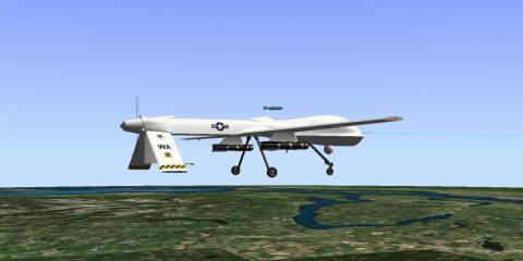
Predator
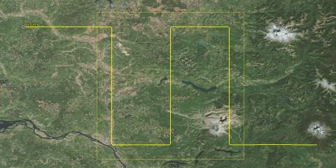
Predator Flight Route
Synthetic Aperture Radar
Predator will use a Synthetic Aperture Radar (SAR) to view the targets. You can use a Sensor object to model its field of regard.
- Use the Insert STK Objects () tool to insert a Sensor (
 ) object using the Insert Default () method.
 - When the Select Object window opens, select Predator () and click OK.
- Rename the Sensor object "SAR."
- Open SAR's () properties ().
- On the Basic - Definition page, change the Sensor Type: to SAR.
- Make the following Synthetic Aperture Radar - Elevation Angles changes:
- Click OK.
| Option | Value |
|---|---|
| Min: | 20 deg |
| Max: | 80 deg |
Connect Introduction
The Connect module provides you with an easy way to connect with STK and work in a client-server environment. You can use the library shipped with Connect to easily build applications that communicate with STK. This library contains functions, constants and other messaging capabilities that you can use to connect third-party applications to STK. With Connect, optional diagnostic messages can be generated. Additionally, Connect allows you to override the standard messaging and modify it or use your own messaging format for compatibility with third-party applications. These features allow you to better control the messaging environment.
Connect communicates with STK and 3D Graphics so you can visualize events in real-time. For instance, you can use Connect to feed real-time telemetry data from the launch and early orbit of a mission. As a scenario, the data can be viewed in 2D or 3D to visualize the mission and assist in understanding and resolving any issues that may arise.
Prior to building connect commands, it would be a good idea to view the selected Connect help files.
- Getting Started with Connect.
- Example Connect Command.
- Connect Command Syntax Elements Command Syntax Elements.
Take some time to view all the help files associated with Integrating with STK. The above help files will help you to understand the Connect commands you are building and sending to this scenario.
Ampersand Operator in Excel
Building Connect commands are easy to do using the Ampersand Operator in Excel. The Ampersand operator separates the different arguments to be combined in a text string.
Create New Targets
The New Command is used to create a new scenario or add a new object to the current scenario.
- Bring the workbook to the front.
- Copy and paste or type the following text string to cell B8: "New" & " " & "/" & " " & "Target" & " " & A2
- If amp; appears after each Ampersand, remove it prior to going to step 4. As you progress through this exercise, remove amp; whenever it is inserted into the Excel spreadsheet. A quick way to accomplish this is to click Find & Search in the Excel toolbar. When the Find and Replace window appears, type amp; in the Find what: field. Leave the Replace with: field blank. Click Replace All then close the Find and Replace window.
- Select cell B8
- Go to the formula bar, highlight and copy all of the text.
- Select cell B2, type the = sign, paste the text string from the formula bar, and click the Enter key on your keyboard.
- Expand column B if desired to read the connect command.
- Click cell B2. Place your cursor on the small black box in the lower right corner of the cell and it will turn into a small plus sign. Hold down your left mouse button and drag the box to cell B6 to complete all your New commands.
When you copy and paste into a cell, make sure you double click the cell prior to pasting text into the cell.
The following picture breaks down the text string:
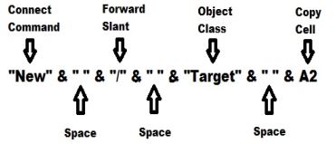
Ampersand Operator

Formula Bar
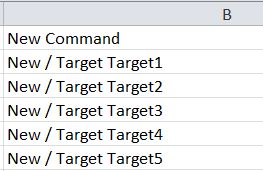
New Commands
The command will create five new Target objects in your scenario.
Set the Target Positions
The SetPosition command is used to set the position of a facility, place, target or area target.
- Copy and paste the following text string to cell F9: "SetPosition" & " " & "*/Target/" & A2 & " " & "Geodetic" & " " & D2 & " " & E2 & " " & "Terrain"
- Remove amp; by using the Find & Select Replace method.
- Select cell F9.
- Go to the formula bar, highlight and copy all of the text.
- Select cell F2, type the = sign, paste the text string from the formula bar, and click the Enter key on your keyboard.
- Expand column F if desired to read the connect command.
- Click cell F2. Place your cursor on the small black box in the lower right corner of the cell and it will turn into a small plus sign. Hold down your left mouse button and drag the box to cell F6 to complete all your SetPosition commands.
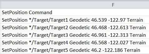
SetPosition Command
The SetPosition command will move the Target objects to the spcified Geodetic coordinates and place them on top of the terrain.
Transfer the Commands to STK
There are many ways to transfer Connect commands into STK. For your purposes, you can use a tool that comes with the STK install. It is called the API Demo Utility.
- Bring STK to the front.
- Open the View menu and select HTML Viewer.
- In the HTML Viewer toolbar, click Browse (
 ).
).
HTML Utilities
Sample HTML Utilities are included with STK and available for download from the AGI Web site. Sample HTML utilities are available for common analysis, parallel processing, creating and manipulating objects, importing data, STK automation, and view control.
- In the Open window, select Example HTML Utilities.
- Expand the STK Automation and then API Demo folders.
- Open API Demo Utility.htm.
- Ensure that any text in the Code Sandbox is removed.
The API Demo Utility will allow you to send Connect commands into the current scenario. This is a great tool to use if you're creating Connect commands and practicing with Connect.
Send Connect Commands
- Return to the Excel workbook.
- Select cells B2 through B6.
- Copy the cells by clicking Ctrl + C on your keyboard.
- Return to STK and paste all five New commands into the API Demo Utility Code Sandbox.
- Return to the Excel workbook and copy the cells F2 through F6 by clicking Ctrl + C on your keyboard.
- Return to STK and paste all five SetPosition commands into the API Demo Utility Code Sandbox beneath the five New commands.
- Click the Run Code button.
- Bring the 2D Graphics window to the front and zoom in to the target area so you can see all five targets.
- Open Target1's (
 ) properties (). On the Basic - Position page, you can see the correctly entered Latitude and Longitude plus Use terrain data is enabled.
 - Remove the Connect commands from the Code Sandbox.
- Return to the Excel workbook.
![]()
Code Sandbox
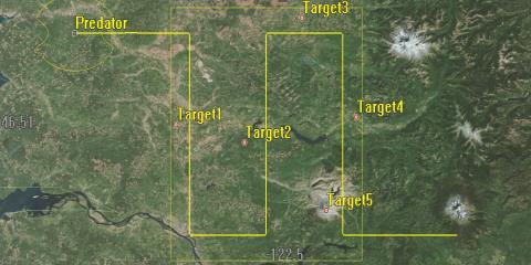
Targets
Show the Target Model
The VO Model command is used to assign a model to a facility, place, target or vehicle (any type). The Target objects currently have their models turned off in the 3D Graphics window.
- Return to Target1's () properties ().
- Select to the 3D Graphics - Model page. Note that in the Model field, Show is disabled.
- Close Target1's () properties ().
- Bring the Excel workbook back to the front.
- Copy and paste the following text string to cell G10: "VO" & " " & "*/Target/" & A2 & " " & "Model Show On"
- Remove amp; by using the Find & Select Replace method.
- Select cell G10.
- Go to the formula bar, highlight and copy all of the text.
- Select cell G2, type the = sign, paste the text string from the formula bar, and click the Enter key on your keyboard.
- Expand column G if desired to read the connect command.
- Click cell G2. Place your cursor on the small black box in the lower right corner of the cell and it will turn into a small plus sign. Hold down your left mouse button and drag the box to cell G6 to complete all your VO Model commands.
Add Three (3) Meters of Height to the Target Objects
The SetHeightAboveGround command is used to set the height above ground of a facility, place or target. The Target objects' center points are currently located right on the surface of the terrain. SetHeightAboveGround is a great command to add additional height to an object to simulate the actual height of an object such as an antenna, sensor, observation platform, tower, etc.
The default units Connect distance unit is meters.
- Copy and paste the following text string to cell H11: "SetHeightAboveGround" & " " & "*/Target/" & A2 & " " & "3"
- Remove amp; by using the Find & Select Replace method.
- Select cell H11.
- Go to the formula bar, highlight and copy all of the text.
- Select cell H2, type the = sign, paste the text string from the formula bar, and click the Enter key on your keyboard.
- Expand column H if desired to read the connect command.
- Click cell H2. Place your cursor on the small black box in the lower right corner of the cell and it will turn into a small plus sign. Hold down your left mouse button and drag the box to cell H6 to complete all your SetHeightAboveGround commands.
Transfer the Commands to STK
You can now move the VO Model and SetHeightAboveGround commands to the API Demo Utility.
- Copy and paste all five VO Model commands to the API Demo Utility.
- Copy and paste all five SetHeightAboveGround commands to the API Demo Utility.
- Click the Run Code button.
- Open Target1's () properties (). On the Basic - Position page, note that Height Above Ground: is now set at 0.003 km.
- Select the 3D Graphics - Model page. In the Model field, note that Show is now enabled.
- Close Target1's () properties ().
- Remove the Connect commands from the Code Sandbox.
- Return to the Excel workbook.
Target Object AzEl Masks
You need to take terrain into consideration when using the SAR. The SetAzElMask (Facility, Place & Target) command is used to set the azimuth-elevation mask for a facility, place or target.
- Copy and paste the following text string to cell I12: "SetAzElMask" & " " & "*/Target/" & A2 & " " & "Terrain"
- Remove amp; by using the Find & Select Replace method.
- Create the SetAzElMask commands for cells I2 through I6.
The commands you just created will create 360 degree AzEl Masks which will use the analytical terrain file loaded earlier in the scenario.
Use AzEl Masks for Accesses
You need to enable the AzEl Masks to be used during an access (i.e. when the SAR Sensor object can see "Access" the Target objects). The SetConstraint (Facility, Place & Target) command is used to set a constraint for a facility, place or target. In this instance, to set the Access constraint.
- Copy and paste the following text string to cell J13: "SetConstraint" & " " & "*/Target/" & A2 & " " & "AzElMask On"
- Remove amp; by using the Find & Select Replace method.
- Create the SetConstraint commands for cells J2 through J6.
- Save your workbook.
Transfer the Commands to STK
You can now move the SetAzElMask and SetConstraint commands to the API Demo Utility.
- Copy and paste all five SetAzElMask commands to the API Demo Utility.
- Copy and paste all five SetConstraint commands to the API Demo Utility.
- Click the Run Code button.
- Open Target1's () properties () and select the Basic - AzElMask page. Note that Use: is set at Terrain Data and Use Mask for Access Constraint is enabled.
- Close Target1's () properties ().
Again, the purpose of this scenario is to show you how to use an Excel workbook to quickly build a scenario by quickly building STK Connect commands and transferring them to STK using the API Demo Utility.
Build a Connect Command in Excel
At this point, use the Excel workbook and try to build an STK connect command that will create an access between the SAR Sensor object and all five Target objects. Go to the Connect Command Library and find the Access command. Use the above steps to create five commands, transfer them to the API Demo Utility and run the code.
Save your work!
 Visit AGI.com