Aviator VTOL and Terrain Following
STK Professional and Aviator.
The results of the tutorial may vary depending on the user settings and data enabled (online operations, terrain server, dynamic Earth data, etc.). It is acceptable to have different results.
Watch the following video, then follow the steps below incorporating the systems and missions you work on (sample inputs provided).Problem Statement
You are using STK to create a pre-brief of a future check-ride for a new helicopter pilot who will be flying search and rescue (SAR) missions in the vicinity of Mount Whitney. The check-ride will consist of taking off from a local helipad, navigating to three checkpoints, and returning back to the airfield for a landing. Part of the check-ride will demonstrate the pilot's ability to fly above the terrain (terrain following) at 1000 feet above ground level (AGL) altitude. You will use STK to familiarize the student pilot with the flight route and terrain features prior to the actual check ride.
Solution
Using STK
Create a New Scenario
Create a new scenario using the default analysis time period.
- Launch STK (
 ).
). - Create a scenario.
- Name the scenario "Advanced_Aviator."
- Use the default analysis time period.
SAVE OFTEN!
Add Terrain
Add analytical terrain from a local file. Microsoft Bing Maps can be used for imagery. However, imagery is not required.
- Open the scenario object’s properties (Advanced_Aviator).
- Browse to the Basic – Terrain page.
- Disable Use terrain server for analysis.
- Click OK.
- Launch the Globe Manager (
 ) from the 3D Graphics window toolbar.
 - Use the Add Terrain/Imagery (
 ) option in the Globe Manager () to load your terrain file (*.pdtt) both analytically and to the globe in the 3D Graphics window.
 - Browse to C:\Program Files\AGI\STK 11\Help\stktraining\imagery and select PtMugu_ChinaLake.pdtt.
- Click Yes when prompted to Use Terrain for Analysis.
Declutter the 3D Graphics Window
Since you're using terrain in the 3D Graphics window, a common user preference is to use
- Bring the 3D Graphics window to the front.
- Right click on the 3D Graphics window and select Properties (
 ).
). - On the Details page, find the Label Declutter field and check Enable.
- Click OK.
Aviator Catalog Manager
Aviator provides a catalog structure for the loading and saving of aircraft, airports, navaids, runways, VTOL points, and waypoints. Each of these elements of a mission has an associated catalog in STK.
- Extend the Utilities menu.
- Select the Aviator Catalog Manager.
- Expand Runway, and select ARINC424 runways.
- Click the Use Master Data File (
 ) button.
 - Browse to <install directory>\Help\stktraining\samples directory.
- Select the FAANFD18 option.
- Click Open.
- When you return to the Aviator Catalog Manager, click Save.
- Close the Aviator Catalog Manager.
Add the Waypoints
There are multiple ways to design waypoints in STK. For this scenario, you will fly direct to waypoints that can easily be inserted into your scenario using the Place ( ) object and the Search Tool or the Define Properties method.
- If you have an Internet connection, use the Search tool to add the following place objects into the scenario.
- Dunmovin, CA
- Olancha Peak, CA
- Mount Whitney, CA
- Insert a Place () object using the Define Properties () method.
- On the Basic - Position page, make the following Position field changes:
- Rename the Place object "Dunmovin."
- Follow the same steps above to add OlanchaPeak and MountWhitney to the scenario. Here are their latitude and longitudes.
If you don't have an Internet connection, use the Define Properties () methods to add waypoints to the scenario. The steps are below to help you.
| Option | Value |
|---|---|
| Latitude: | 36.0963 deg |
| Longitude: | -117.965 deg |
| Option | Value |
|---|---|
| Olancha Peak Latitude: | 36.2665 deg |
| Olancha Peak Longitude: | -118.117 deg |
| Option | Value |
| Mount Whitney Latitude: | 36.5789 deg |
| Mount Whitney Longitude: | -118.291 deg |
Aviator
Now that you have added waypoints you can fly to, it's time to plan the mission using Aviator. You will add wind, build a popular type of high altitude rescue helicopter, and create a flight path to and from Mount Whitney.
- Insert an Aircraft (
 ) object into the scenario using the Insert Default () method.
 - Rename the Aircraft object "CheckRide."
- Open CheckRide's () properties ().
- On the Basic - Route page, change the Propagator to Aviator.
- Click Apply.
Flight Path Warning
Aviator performs best in the 3D Graphics window when the surface reference of the globe is set to Mean Sea Level. You will receive a warning message when you apply changes or click OK to close the properties window of an Aviator object with the surface reference set to WGS84. It is highly recommended that you set the surface reference as indicated before working with Aviator.
- When the Flight Path Warning window opens, click Set Globe Reference to MSL.
- Click OK.
Mission Window
The
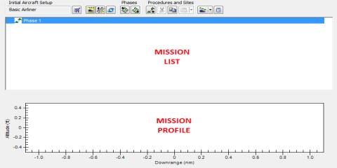
List and Profile
Initial Aircraft Setup toolbar
The buttons on the
Mission Wind Model
The
- Click the Mission Wind Model icon.
- Change Model Type: to Constant Bearing/Speed.
- Change Wind Speed to 20 nm/hr
- Click OK.
- Click Apply.
View the Wind in the Mission Profile
As you build the mission, you can view the wind in the Mission Profile.
- Right-click in the Mission Profile.
- Select Profile Options/Properties.
- Enable the Secondary Y Axis.
- Select Course Crosswind.
- Click OK.
Select Aircraft
Select the aircraft to be used for the Mission.
- Click the Select Aircraft (
 ) button on the Initial Aircraft Setup toolbar.
 - When the Select Aircraft window appears, right-click on Basic Helicopter and select Duplicate (
 ).
). - Rename the Basic Helicopter Copy, "CheckRide."
- Ensure CheckRide is selected and click OK.
- Click Apply.
Enable Terrain Following
You want to ensure the aircraft follows the terrain. To do this, you need to enable the Terrain Follow performance model.
- Click the Aircraft Properties (
 ) button on the Aircraft Setup toolbar.
 - When the CheckRide window appears, right-click in the Performance Models: field and select Add New Model Type.
- In the Add New Model Type window, click TerrainFollow in the Models: field. This automatically moves it to the New Types: field.
- Click OK.
Model Helicopter General Characteristics
You are modeling a high altitude rescue helicopter. The helicopter's empty weight is 3951 pounds. You will add 2000 pounds to that total to account for crew and equipment. Let's input the properties.
- Click the Default Configuration button (
 ).
). - Make the following changes on the Basic page.
| Option | Value |
|---|---|
| Empty Weight: | 5951lb |
| Max Landing Weight: | 7903 lb |
- Select the Stations tab.
- Click Internal Fuel.
- Make the following changes in the order shown:
| Option | Value |
|---|---|
| Initial state: | 1500 lb |
| Capacity: | 1530 lb |
- Click Apply.
Performance Models
Continue building the helicopter to specifications.
- In Performance Models: select Climb Built-In Model.
- Change Altitude Rate: to 1600 ft/min.
- Select Cruise Built-In Model.
- Change the Default Cruise Altitude to 15000 ft.
- Make the following changes to Max Performance:
- In the Performance Models, select VTOL Built-In Model.
- In the Translation Maneuver field, change Rate to 25 nm/hr.
- Click Save and then click Close.
- Click Apply.
| Option | Value |
|---|---|
| Airspeed: | 131 nm/hr |
| Fuel Flow: | 560 lb/hr |
You are using a constant wind speed of 20 nm/hr. The Translation Maneuver Rate default is approximately nine (9) nm/hr. Since you will be taking off into the wind, you need to compensate for the strong headwind.
Specify Phase Performance Models
Select Performance Models for the aircraft to be applied only to the current Mission Phase. In this case, you need to link Terrain Following to the catalog.
- Click the
 ) button.
 - When the Phase 1 properties window opens, locate the Model Type column.
- Right-click on TerrainFollow and select Link to Catalog.
- When the Link to Catalog (TerrainFollow) window appears, click OK.
- Click OK to close the Phase 1 properties window.
Takeoff Procedure
You are taking off from a helipad. You can model that helipad using the Aviator Catalog Manager and selecting it.
- In the Mission List, right-click on Phase 1.
- Select the Insert First Procedure for Phase (
 ) option.
 - In the Select Site Type: field select VTOL Point from Catalog (
 ).
). - Type Ridgecrest in the Filter: field and click the Enter key.
- Select SCE RIDGECREST SERVICE CENTER H1 and click Next.
- In the Select Procedure Type: field, select Vertical Takeoff.
- In the Heading field, enable Heading into Wind.
- Click Finish.
- Click Apply.
Forward Flight
- In the Mission List, right-click on Vertical Takeoff.
- Select Insert Procedure After ().
- In the Select Site Type: field select End of Previous Procedure.
- Click Next.
- In the Select Procedure Type: field, select Transition to Forward Flight.
- In the Transition Course, enable Transition into Wind.
- Click Finish.
- Click Apply.
Add STK Object Waypoints
An
Proceed to Dunmovin
- In the Mission List, right-click on Transition to Forward Flight.
- Select Insert Procedure After ().
- In the Select Site Type: field select STK Object Waypoint.
- Change the Name: to Dunmovin.
- In the Link To: field select Dunmovin.
- Click Next.
- In the Select Procedure Type: field, select Basic Point to Point.
- Change Enroute Cruise Airspeed to Max Performance Airspeed.
- Click Finish.
- Click Apply.
Proceed to Olancha Peak
- In the Mission List, right-click on Dunmovin.
- Select Insert Procedure After ().
- In the Select Site Type: field select STK Object Waypoint.
- Change the Name: to Olancha.
- In the Link To: field select Olancha Peak.
- Click Next.
- In the Select Procedure Type: field, select Basic Point to Point.
- Change Enroute Cruise Airspeed to Max Performance Airspeed.
- Click Finish.
- Click Apply.
Terrain Following to Mount Whitney
- In the Mission List, right-click on Olancha.
- Select Insert Procedure After ().
- In the Select Site Type: field select STK Object Waypoint.
- Change the Name: to Whitney.
- In the Link To: field select Mount Whitney.
- Click Next.
- In the Select Procedure Type: field, select Terrain Following.
- Change AGL Altitude: to 1000 ft
- Change Terrain Following Airspeed to Max Performance Airspeed.
- Click Finish.
- Click Apply.
Reverse Point to Point
After arriving at Mount Whitney, the pilot will turn and fly back to Ridgecrest to land. To save time and not rebuild the reverse course, you can use Reverse Point to Point Procedure order.
- In the Mission List, right-click on Whitney.
- Extend the Tools and Wizards menu.
- Select Reverse Point to Point Procedure Order option.
- When the Reverse Point to Point Procedures window appears, click OK.
- In the Mission List, right-click on Whitney.
- Select Insert Procedure After ().
- In the Select Site Type: field select Super Procedure.
- Click Next.
- Click Load Procedures from Clipboard.
- Click Finish.
- Click Apply.
Land at Ridgecrest
- In the Mission List, right-click on Super Procedure Site.
- Select Insert Procedure After ().
- In the Select Site Type: field select VTOL Point from Catalog ().
- Type Ridgecrest in the Filter: field and click the Enter key.
- Select SCE RIDGECREST SERVICE CENTER H1.
- Click Next.
- In the Select Procedure Type: field, select Transition to Hover.
- Change Altitude to AGL and the value to 50 ft.
- In Transition Options, enable the Transition into Wind option.
- Click Finish.
Vertically Land Back at Ridgecrest
- Right-click on Transition to Hover.
- Select Insert Procedure After ().
- In the Select Site Type: field select VTOL Point from Catalog ().
- Select SCE RIDGECREST SERVICE CENTER H1 and click Next.
- In the Select Procedure Type: field, select Vertical Landing.
- Change Heading Mode: to Heading into Wind.
- Click Finish.
- Click Apply.
Mission List and Mission Profile
When you have finished building your mission, you can view your procedures and profile in the mission window. Your profile view may be different due to current wind conditions.
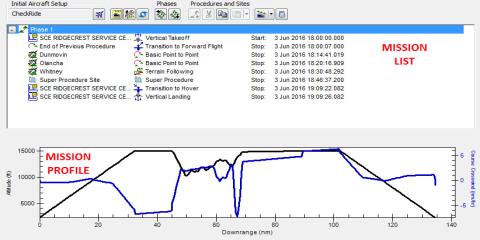
Completed Mission List and Mission Profile
Fuel Consumed
If you recall, you began the mission with 1500 pounds of fuel. You can easily check how much fuel is remaining when you land.
- In the Mission List, right-click on Vertical Landing.
- Select the Profile Data at Final State option.
- Locate Fuel Consumed and note the value.
- Close the data window.
- Click OK to close CheckRide's () properties ().
Create a Custom Report
At this point, you can zoom to CheckRide and play the scenario to see how each procedure looks in the 3D Graphics window. When finished, add a custom dynamic display to the 3D Graphics window that shows mission parameters for the flight.
- Right-click on CheckRide () and open the Report & Graph Manager (
 ).
). - In the Styles field, enable Show Reports and disable Show Graphs.
- Right-click on the My Styles folder.
- Select New and click Report.
- Name the report Mission Profile and click the Enter key to open the report's properties.
- Expand (
 ) the Flight Profile By Time Data Provider
 - Move (
 ) the following data providers to the Report Contents list in the following order:
 - Time
- DownRange
- Altitude
- Altitude-AGL
- FuelConsumed
- Click OK and close the Report & Graph Manager.
If required , you can add any data providers of interest. Since you're going to put this report on the 3D Graphics window, it's a good idea to only insert a few parameters.
Add a Data Display
- Open CheckRide's () properties () and browse to the 3D Graphics - Data Display page.
- Click the Add... button.
- In the Add a Data Display window, locate and select the Mission Profile report in the Styles field.
- Click OK.
- You can modify the look of the display if required using the Position, Appearance, and Background fields.
- When finished, click OK.
If you reset and then play the scenario, you can see the Mission Profile information on the 3D Graphics window.

Data Display
Save Your Work!
 Visit AGI.com