This exercise takes you through the process of creating a body mask (BMSK) file with the AzEl Mask tool and using it to constrain visibility calculations. Also, you will be able to visualize the body mask in 3D.
The results of the tutorial may vary depending on the user settings and data enabled (online operations, terrain server, dynamic Earth data, etc.). It is acceptable to have different results.
Watch the following video, then follow the steps below incorporating the systems and missions you work on (sample inputs provided).Create a Scenario
- Click the Create a New Scenario button.
- Enter the following in the New Scenario Wizard:
- When you finish, click OK.
- When the scenario loads, click Save (
 ). A folder with the same name as your scenario is created for you in the location specified above.
 - Verify the scenario name and location and click Save.
- Right-click on the scenario (
 ) and open the Properties (
 ).
). - Select the Basic - Terrain page.
- Disable the Use terrain for analysis option.
- Click OK to apply changes and dismiss the Properties Browser.
| Option | Value |
|---|---|
| Name | AzElMaskTool |
| Location | C:\Documents and Settings\<user>\My Documents\STK 11 (x64)\ |
| Start | 1 Jul 2016 16:00:00.000 UTCG (NOTE: accept defaults if you are not completing the L3 quiz) |
| End | + 1 day (NOTE: accept defaults if you are not completing the L3 quiz) |
If you plan to complete the L3 quiz at the end of the tutorial, disable the Terrain Server.
Obtain an Archived Satellite Database
- Obtain an Archived Satellite Database.
- Open the Scenario's () Properties ().
- Select the Basic - Database page.
- Click the "Update Database Files..." button.
- Select the following options:
- Click Update.
- Click OK on the "Database update complete" pop up notification.
- Close the Update Satellite Database panel.
- Click OK to dismiss the Properties Browser.
| Option | Value |
|---|---|
| Option | Obtain Archived Database |
| Database Information | Specific Database |
| Specific Database File | stkAllTLE |
| Archive Date | 1 Jul 2016 16:00:00.000 UTCG |
Insert a Satellite from an Archived Database
- Using the Insert STK Objects tool (
 ), choose Satellite (
 ) as your object to be inserted and select From TLE File in the Method pane.
 - Click Insert.
- Select stkAllTLE.tce and click Open.
- Click Modify... and disable the "On propagation, automatically retrieve elements" option.
- Click OK.
- In the Common Name text box, replace the * with "Iridium 10" and click Search.
- Select IRIDIUM 10 and click Insert.
- Click Close to dismiss the Insert From Satellite Database panel.
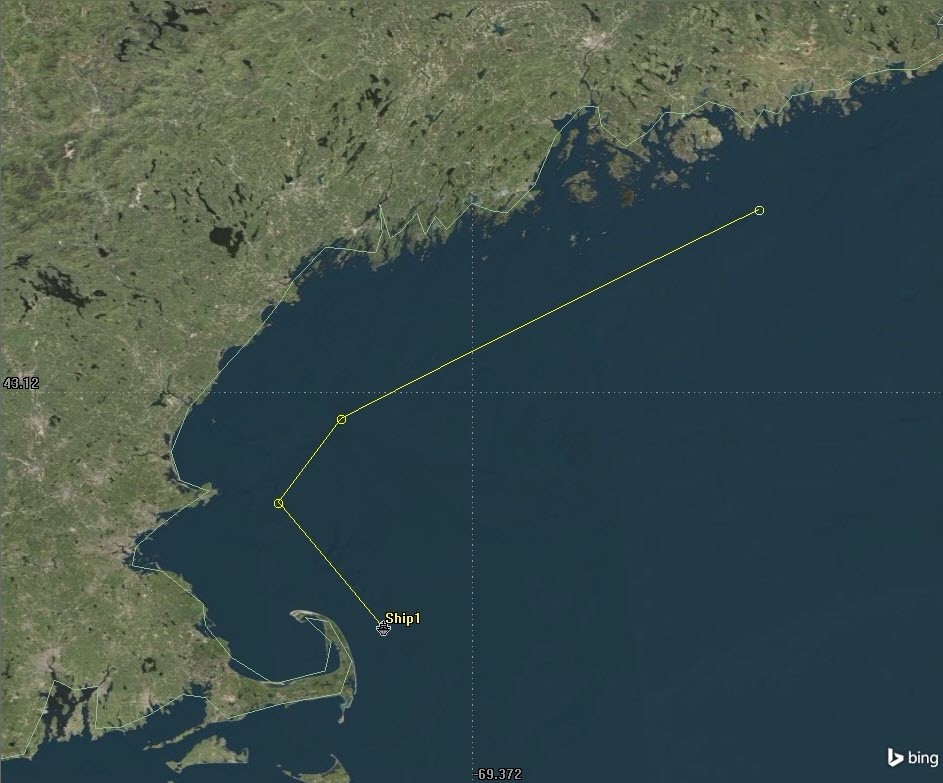
Insert a Ship
- Using the Insert STK Objects tool (), insert a default Ship.
- Open the ship's (
 ) properties ().
 - Select the Basic - Route page.
- Click Insert Point four times to insert four waypoints.
- Manually enter the lat and lon for each of the waypoints:
- Click OK to accept the waypoints and dismiss the Properties Browser.
- Zoom To the Ship () in the 3D Graphics window.
| Latitude | Longitude |
|---|---|
| 42.0 deg | -69.8 deg |
| 42.6 deg | -70.3 deg |
| 43.0 deg | -70.0 deg |
| 44.0 deg | -68.0 deg |
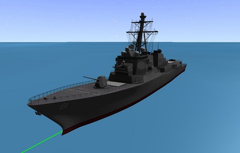
Model a Sensor
- Using the Insert STK Objects tool (), attach a default sensor (
 ) to the Ship object.
 - Open the sensor’s () Properties ().
- Select the Basic - Location page.
- Seelect Fixed at the Location Type.
- Set the X axis adjustment of 0.04 km.
- Set the Z axis adjustment of 0.01 km.
- Select the Basic - Definition page.
- Set the Sensor Type to Complex Conic.
- Set the Outer Half Angle to 180 deg.
- Click OK to accept those changes and close the Properties Browser.
You can also select 3D Model as the Location Type and use the ship model's attach points or the sensor's 3D Graphics Vertex Offset properties to position the sensor.
When you position the sensor origin, make certain that it is outside the shell of the model; otherwise the AzEl Mask tool will not work.
For this exercise you will position the sensor origin on or slightly above the forward deck, close to the superstructure. You can check your settings by clicking Apply and viewing the 3D Graphics window.
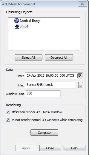
Create a BMSK File
Next you will use the AzEl Mask tool to create a BMSK file that can be used in access computations and visualization.
- Right-click the sensor () in the Object Browser.
- Select Sensor - AzEl Mask… A white window, possibly containing one or more black shapes, will appear, along with the AzElMask dialog. (If no black shape appears, it only means there is no obstruction in the direction being shown in the window.)
- Select the ship as the Obscuring Object.
- Click the File browse (
 ) button to specify a file name and location for the BMSK file.
 - Set the File name to SensorBMSK.bmsk.
- Click Save.
- Set the Window Dim field to the largest possible size, so that the entire window is shown and not extended off the screen, and in the foreground and not obscured by other screen objects. This will allow for the most accurate mask with the finest possible detail.
- Click Apply to set the new window dimensions, and then click Compute to create the BMSK file.
- Close the AzEl Mask tool.
For targeted sensors, it is important to show the sensor at a time at which it is targeted to an object. The sensor is not displayed when there are no targets in view.
Use the BMSK File to Constrain Access
Now you will configure the sensor to use the BMSK file as a limiting factor in visibility calculations.
- Open the Access tool (
 ) and compute Access from the sensor () to Iridium 10.
 - Generate an Access report between the satellite and the sensor. This will determine when you have periodic access.
- Save this report as a .csv file (
 ) so you can compare it with another report later.
 - Open the sensor's () Properties ()
- Select the Basic - Sensor AzEl Mask page
- Set the Use option to MaskFile and use the Mask File browse button to locate your BMSK file. (Make certain to change the 'Files of type' filter to *.bmsk.)
- Enable the Use Mask for Access Constraint option and click Apply. Navigate to the Constraints - Basic page to see the Sensor AzElMask has been enabled.
- Click OK to accept changes and dismiss the Properties Browser.
- Recreate the access report. You will notice the effects of the mask file on the results.
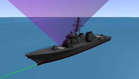
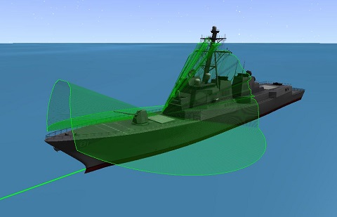
Visualize the Body Mask in 3D
Finally, create a 3D representation of the body mask and superimpose it on the view of the sensor cone.
- Open the sensor's () Properties ().
- Select the 2D Graphics - Projection page:
- Set the Show Intersections to None.
- Enable the Use Constraints under Field of View and select SensorAzElMask.
- Click Apply.
- On the 3D Graphics - Projection page:
- Set Type to None.
- Enable Use Extension Distance as Maximum.
- Set the Space Projection to a small value (e.g., 35 m) to show only the mask immediately around the ship.
- Click OK to accept changes and dismiss the Properties Browser.
- Check out the view in the 3D Graphics window. (You may need to click Reset to refresh the sensor display.)
 Visit AGI.com