STK Professional, STK SatPro and Communications.
The results of the tutorial may vary depending on the user settings and data enabled (online operations, terrain server, dynamic Earth data, etc.). It is acceptable to have different results.
This brief tutorial is designed to introduce the CommSystem object, its setup and use in the analysis of RF interference phenomena.
In this exercise you will:
- Set up a communications link between a geostationary (GEO) satellite and a ground station.
- Use the Satellite Walker tool to define a constellation of low-earth orbiting (LEO) satellites.
- Set up the CommSystem object to compute interference between transmitters in the LEO constellation and the GEO to ground station link.
- Observe the effects of the interference in the 2D and 3D Graphics windows.
- Generate CommSystem object reports detailing the effects of the interference on communications link performance indicators such as bit error rate (BER).
- Impose an Interference constraint and observe its effects in a CommSystem object report.
Create a Scenario
Start by creating a scenario.
- Create a scenario (
 ) and name it InterferenceAnalysis.
 - Change Start: to 1 Jul 2016 16:00:00.000 UTCG and Stop: to + 24 hrs.
Save Often!
Turn Off Terrain Server
Analytical terrain is not required in this scenario, therefore, turn off Terrain Server.
- Open InterferenceAnalysis's properties.
- Browse to the Basic - Terrain page.
- Disable Use terrain server for analysis.
- Click OK.
Introduce the Geostationary Satellite
Create a Satellite ( ) object which will function as the geostationary communication satellite.
- Use the Insert STK Objects tool to insert a Satellite () object using the Orbit Wizard (
 ) method.
 - Make the following changes:
- Click OK.
| Option | Value |
|---|---|
| Type: | Geosynchronous |
| Satellite | GEO |
| Subsatellite Point: | -100 deg |
| Inclination: | .25 deg |
Introduce the Ground Station
- Use the Insert STK Objects tool to insert a Facility (
 ) object using the From Standard Object Database (
 ) method .
 - When the Search Standard Object Data window opens, enter Castle Rock in the Name: field.
- Click Search.
- Select the first Castle Rock Teleport in the Results: list and click the Insert button.
- Close the Search Standard Object Data window.
Adjust Ground Altitude
Remove the attached AzElMask file.
- In the Object Browser, right click on Castle_Rock_Teleport () and select Properties (
 ).
). - On the Basic - Position page, enable Use terrain data..
- Click Apply.
- Browse to the Basic - AzElMask page and make the following changes:
| Option | Value |
|---|---|
| Use: | None |
| Use Mask for Access Constraint | disable |
Click OK.
GEO Transmitter
You will use a Medium Transmitter Model on GEO.
- Use the Insert STK Objects tool to insert a Transmitter (
 ) object using the Insert Default method.
 - When the Select Object window opens, select GEO () and click OK.
- Rename the Transmitter object GEOXmtr.
- Open GEOXmtr's () properties ().
- On the Basic - Definition page, make the following changes:
- Click OK.
| Option | Value |
|---|---|
| Type: | Medium Transmitter Model |
| Frequency: | 1.5 GHz |
| Gain: | 30 dB |
Castle Rock Teleport Receiver
You will use a Complex Receiver Model on Castle_Rock_Teleport.
- Use the Insert STK Objects tool to insert a Receiver (
 ) object using the Insert Default method.
 - When the Select Object window opens, select Castle_Rock_Teleport and click OK.
- Rename the Receiver object CRTRcvr.
- Open CRTRcvr's () properties ().
- On the Basic - Definition page make the following changes:
- Click Apply.
- Select the Antenna tab.
- Change the Diameter: value to .25 m.
- Select the Orientation tab and make the following changes:
- Click OK.
| Option | Value |
|---|---|
| Type: | Complex Receiver Model |
| LNA Gain: | 30 dB |
| Option | Value |
|---|---|
| Azimuth: | 172.4 deg |
| Elevation: | 44.3 deg |
Simple Link Budget
Create a link budget between CRTRcvr and GEOXmtr.
- In the Object Browser, right click on CRTRcvr () and select Access (
 ).
). - When the Access Tool opens, in the Associated Objects list, expand GEO () and select GEOXmtr ().
- Go to the Reports field and click the Link Budget... button.
- When the report opens, scroll to the right and locate the BER column (Bit Error Rate).
- Close the Link Budget report and close the Access tool.
- Open the Analysis menu and select Remove All Accesses.
For the purposes of your analysis, anything less than 1.000000e-007 is acceptable.
Introduce the Low Earth Orbit (LEO) Constellation
The LEO constellation of satellites have transmitters which may be interfering with your communication link between GEO and Castle_Rock_Teleport.
- Use the Insert STK Objects tool to insert a Satellite () object using the Orbit Wizard () method.
- Make the following changes:
- Click OK.
| Option | Value |
|---|---|
| Type: | Circular |
| Satellite | LEOSat |
| Altitude: | 2000km |
Reuse a Transmitter
The transmitter on LEOSat has the same properties as the transmitter on GEO. You can reuse the existing transmitter. This is a quick way to create a new object having identical properties to an object already existing in the scenario.
- In the Object Browser, select GEOXmtr () and click the Copy (
 ) button.
 - Select LEOSat and click the Paste (
 ) button.
 - Expand LEOSat ().
- Rename the Transmitter object "LEOXmtr".
The Walker Tool
The Walker Tool makes it easy to generate a Walker constellation using the Two Body, J2, J4, or SGP4 orbit propagators. The original satellite that you defined is referred to as the seed satellite, while the satellites generated using the Walker tool are referred to as the children.
If the seed satellite has sub-objects such as transmitters, the sub-objects are also created for each of the child satellites.
- Select LEOSat () in the Object Browser.
- Open the Satellite menu item and select Walker.
- When the Walker Tool opens, make the following changes:
| Option | Value |
|---|---|
| Number of Sats per Plane: | 3 |
| Number of Planes: | 3 |
- In the Constellation field, enable Create Constellation.
- Enter LEOGroup as the name.
- Click the Create Walker button.
- When finished, click the Close button
There are a couple of things to note at this point. If you look at the Object Browser, you have a Constellation object named LEOGroup. LEOGroup contains each new LEO Satellite object that you created. You can see each individual LEO Satellite object too. The original LEO Satellite object, LEOSat (the seed satellite), and LEOSat11 are sharing the same spot. Therefore, you no longer need your seed Satellite object.
- Save (
 ) the scenario.
Your seed Satellite object has been saved in the scenario folder for later use if you need it.
- In the Object Browser, select LEOSat.
- Click the Delete button.
- Open the Window menu and select Tile Vertically.
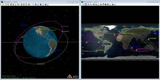
2D and 3D Graphics Windows
- In the 3D Graphics window, use your mouse buttons to view the walker constellation of satellites.
- Click the Play (
 ) button.
 - When you are finished, return to the Animation Toolbar and click Reset (
 ).
).
The CommSystem Object
The CommSystem object models dynamically configured communications links between constellations of transmitters and receivers.
If you don't have a CommSystem ( ) object in the Insert STK Objects tool, you can add it by performing the following steps.
- In the Insert STK Objects tool, click the Edit Preferences... button.
- When the Preferences window opens, find the Define Default Creation Methods field.
- In the Check the "Show" item to display the object in the "New Object" tool, locate and enable Comm System.
- Click OK.
- Use the Insert STK Objects tool to insert a Comm System () object using the Insert Default method.
- In the Object Browser, rename the Comm System object CommSystem.
Constellations
To set up a CommSystem object, you must first organize the relevant communications assets into three groups:
- the transmitter(s) in the communications link of interest
- the receiver(s) in the communications link of interest
- the potentially interfering transmitter(s)
This grouping is accomplished with the help of the STK
- Use the Insert STK Objects tool to insert a Constellation (
 ) object using the Insert Default method.
 - Use step one to insert two more Constellation objects. You should have a total of three new Constellation objects in the Object Browser.
- Starting with the first new Constellation object, rename the three new Constellation objects with the following:
- Transmitter
- Receiver
- InterferenceSources
Interference Sources
Group your potential interference sources.
- Open InterferenceSources () properties.
- In the Objects field, go to the Selection Filter: list.
- Enable Transmitter.
- In the Available Objects list, click the right arrow (
 ) to move all the Transmitter objects to the Assigned Objects list.
 - Locate and select GEO/GEOXmtr in the Assigned Objects list.
- Move (
 ) GEO/GEOXmtr to remove it from the Assigned Objects list.
 - Click OK.
GEOXmtr is not an interference source so you must remove it from the list.
Receiver
There's only one receiver in the scenario. This is part of your communication system.
- Open Receiver's () properties.
- Select CRTRcvr () in the Available Objects list.
- Move () CRTRcvr () it to the Assigned Objects list.
- Click OK.
Transmitter
The transmitter you're focusing on is the GEO transmitter. This is part of your communication system.
- Open Transmitter's () properties.
- Select GEOXmtr () in the Available Objects list.
- Move () GEOXmtr it to the Assigned Objects list.
- Click OK.
Comm System
You have grouped all the objects needed to perform interference analysis using the Comm System object.
- Open CommSystem's () properties ().
- On the Basic - Transmit page, move () the Transmitter constellation from the Available Constellation list to the Selected Constellation list using the right arrow.
- Browse to the Basic - Receive page.
- Move () the Receiver constellation from the Available Constellation list to the Selected Constellation list using the right arrow.
- Browse to the Basic - Interference page.
- Move () the InterferenceSources constellation from the Available Constellation list to the Selected Constellation list using the right arrow.
- Browse to the Interval page.
- Change the Step size: value to 60 sec.
- Click OK.
Increasing the interval step size will reduce the report size.
Determine Interference
Determine if the communication link between GEO and Castle_Rock_Teleport contains interference.
- Save (
 ) your scenario.
 - Select CommSystem () in the Object Browser.
- Open the CommSystem menu item and select Compute Data.
- Return to the Object Browser, right click on CommSystem () and select Report & Graph Manager.
- In the Styles list, ensure Show Reports is enabled.
- Select the Link Information Detailed report and click the Generate... button.
- Locate the BER and BER+I columns.
- Scroll down through the report and compare both columns.
- Leave the report open.
The calculation in this scenario is fast. Should you have a longer, more complicated calculation, there is a progress bar that will appear in the lower right corner of STK. When the progress bar reaches 100%, it will disappear. Your calculation is complete.
BER+I is Bit Error Rate plus Interference.
Are there occasional instances of interference?
Communication Constraints
In this scenario, you are focusing on BERs. Filter the report to those times that communications are degraded. Earlier in the lesson, the BER benchmark was 1.000000e-007 or lower. Set an interference constraint that will report when the communication system is down.
- Open CRTRcvr's () properties ().
- Browse to the Constraints -
- In the BER+I field, enable Min: and set the value to 1e-007.
- Click Apply.
- Return to the Link Information Detailed report and click the Refresh button.
- Scroll down through the BER+I column.
- When finished, close CRTRcvr's () properties (), the Link Information Detailed report, and the Report & Graph Manager.
- Save () your scenario.
The report is only showing those times when the BER is greater than 1.000000e-007 or when the communication link is down. Change other constraints to see how they effect the report.
 Visit AGI.com