STK Professional and Communications.
The results of the tutorial may vary depending on the user settings and data enabled (online operations, terrain server, dynamic Earth data, etc.). It is acceptable to have different results.
Problem Statement
You are performing a UAV training mission . Part of the training is to determine if a small hand-held GPS jammer can interfere with your mission. This jamming device was confiscated from a person who illegally purchased it over the Internet.
Solution
Use STK to model a scenario that analyzes GPS reception. You need to determine if an illegal hand-held GPS jammer can interfere with the reception of GPS signals in the area.
Create a New Scenario
- Launch STK (
 ).
). - Click Create a Scenario.
- In the New Scenario Wizard, name the Scenario object GPS_Jamming.
- Change Start: to 1 Jul 2016 18:00:00.000 UTCG.
- Change Stop: to 2 Jul 2016 18:00:00.000 UTCG.
- Click OK.
SAVE OFTEN!
Scenario RF Environment
Since you're modeling the down link portion of a satellite transmission, you'll enable rain and atmospheric absorption models.
- Open GPS_Jamming's (
 ) properties (
 ).
). - Browse to the RF - Environment page.
- Select the Rain and Cloud & Fog tab.
- In the Rain Model field, enable Use.
- Select the default rain model.
- Select the Atmospheric Absorption tab.
- Enable Use.
- Select the default.
- Click OK.
Using terrain in your analysis would be a good option and it should be considered. On your own, you can call 1.610.981.8875 or Email eval@agi.com to request TIREM and a TIREM license. TIREM is a separate install and license. TIREM would be used instead of the atmospheric absorption model ITU-R P676-9.
Add an Aircraft
For this scenario, simulate the point-to-point flight route of a UAV. You can use the GreatArc propagator.
- Insert an Aircraft (
 ) object.
 - Open the Aircraft's () properties ().
- On the Basic - Route page, click the Insert Point button.
- Manually enter the parameters of each waypoint in the waypoints table starting with the first waypoint.
- Click the Insert Point button four times and make the following changes to waypoints 2 through 5:
- Click Apply.
While inserting new values into each cell in the table, click the Enter key on your keyboard after each entry.
| Option | Value |
|---|---|
| Latitude | 37.1 |
| Longitude | -115.85 |
| Altitude | 8000 ft |
| Speed | 100 mi/hr |
| Turn Radius | 1.0 km |
Altitude, Speed and Turn Radius will copy to each new waypoint. Therefore, you only need to change the latitude and longitude of the remaining waypoints as you build them.
| Waypoint | Latitude | Longitude |
|---|---|---|
| Two | 37.4 deg | -115.85 deg |
| Three | 37.4 deg | -115.75 deg |
| Four | 37.1 deg | -115.75 deg |
| Five | 37.1 deg | -115.85 deg |
Add Realism to Aircraft
To add realism to the aircraft's fixed antenna pattern later in the lesson, you can create roll when your aircraft is in a turn.
- Select the Basic - Attitude page.
- Change the Type to Coordinated Turn.
- Browse to the 3D Graphics - Model page.
- Click the Model File: ellipsis button and select uav.mdl (or the aircraft of your choice).
- Click OK to accept your changes and close the Aircraft object's properties.
- If desired, center your 3D Graphics window on your Aircraft object's flight route.
Create the GPS Jammer Location
The jam team is deploying the hand held GPS jammer near Mount St. Helens. You can use a Place object to simulate their location.
- Using Insert STK Objects tool, insert a Place (
 ) object using the Insert Default method.
 - Rename the Place object GPSJammer.
- Open the GPSJammer's () properties ().
- On the Basic - Position page, make the following changes:
- Click OK.
| Option | Value |
|---|---|
| Latitude | 37.2318 deg |
| Longitude | -115.795 deg |
| Height Above Ground | 3 m |
Model the GPS Network
The UAV is equipped with a GPS receiver . The GPS receiver communicates with the GPS network to determine position information.
You need an archived database of satellite TLEs to complete this lesson and to obtain the same results in any reports or graphs. Below are two ways to bring in the archived database. The first way is by bringing in the file via STK. The second way is by downloading a file from AGI. If desired, try both ways for practice.
Download an Archived Satellite Database Using STK
- Open GPS_Jamming’s properties.
- Browse to the Basic – Database page.
- Click Update Database Files.
- Select Obtain Archived Database.
- Select Specific Database.
- Open the pull-down menu and select stkAllTLE.
- Click Update.
- When the Information window appears, click OK.
- Close the Update Satellite Database window.
- Close the properties window.
Download an Archived Satellite Database from AGI
If you have access to the Internet from another computer but not from the computer with STK, complete the following steps:
- Go to agi.com and LOG IN.
- At the top of the page, click Resources.
- Click Supporting STK Data.
- Click Satellite Database.
- Select Click here to search the archives.
- Make the following selections:
- Click Get Archive.
- Click stkAllTLE20160630.tar.gz (06/30/2016) to download the file.
- Take the file to the computer that has STK installed on it (if you are using a computer with STK, go to the next step).
| Option | Value |
|---|---|
| Satellite Database: | stkAllTLE |
| Archive Date: | June 1016 |
Insert the GPS Satellites
- In the Insert STK Objects tool, insert a Satellite object using the From TLE File method.
- STK download method:
- Browse to C:\ProgramData\AGI\STK 11 (x64)\Databases\Satellite
- Select stkAllTLE.tce.
- AGI download method:
- Browse to the folder where the stkAllTLE20160701.tar.gz file is located.
- Select stkAllTLE20160630.tar.gz and click Open.
- STK download method:
- In the Insert From Satellite Dabase, change Common Name to GPS and click Search.
- Select and insert only GPS BIIF / BIIR / BIIRM satellites. There should be 32 selected satellites.
- Delete GPS_BIIRM-7_34661 from the Object Browser. It’s a reserve satellite.
Remove Unneeded Satellites
You should remove unneeded satellites to declutter the scenario. These are satellites that the aircraft will not have access to during the mission.
- In the Object Browser, right click on the Aircraft () object and select the Access (
 ) tool.
 - Select all GPS satellites in the Associated Objects field.
- Click the Access... button in the Graphs section.
- Use the Access Times graph to determine what satellites are unnecessary.
- Delete one satellite at a time from the Object Browser if it doesn't appear on the Access Times graph.
You want to keep the satellites that are on the graph. These are the satellite you'll have access to during the scenario. The key here is to remove satellites from the Object Browser that are not being reported in the graph. If a satellite had a reported outage that coincides with your scenario analysis period, it's up to you whether or not to remove it.
Clean Up the Access Times
- When finished, you can close the graph and the Access Tool.
- Extend the Analysis menu.
- Select the Remove All Accesses option.
Create a Constellation of Satellites
- Insert a Constellation object using the Define Properties method.
- In Selection filter: enable Satellite.
- Click the Right Arrow to move the selected satellites from the Available Objects list to the Assigned Objects list.
- Click OK.
- Rename the Constellation object “GPS_Sats”.
Model the GPS Transmitter Equipment
You have the scenario level objects in your scenario. Now you can focus on modeling the GPS transmitters.
- Insert a Transmitter (
 ) object using the Insert Default method.
 - When the Select Object window appears, select the first GPS satellite (
 ) in the list and click OK.
GPS Transmitter
You have a generic transmitter attached to the GPS satellite. The next step is to configure the transmitter’s properties. Then you can copy and paste this transmitter to the other GPS satellites since they all have identical equipment.
- Open the Transmitter's () properties ().
- Change Type to GPS Satellite Transmitter Model.
- Change Power to 27.45 W.
- Apply your changes.
Build the GPS Antenna
You will use the default beam specifications settings, but you need to modify the antenna.
- Click the Antenna tab.
- Ensure the GPS Global option is selected.
- Set the Block Type to IIR, L1.
- Set the Efficiency to 80%.
Set the Antenna Polarization
Antennas used in GPS systems are right-hand circularly polarized.
- Click the Polarization tab.
- Enable the Use option.
- Set the Polarization to Right Hand Circular.
Set the Model Specs
For public use, the GPS design uses Coarse/Acquisition code transmitted at a data rate of 1023 kb/sec.
- Select the Model Specs tab at the top of the page.
- Set the Data Rate to 1.023 Mb/Sec.
Set the Antenna Modulator
The GPS Coarse/Acquistion code uses the binary Phase-shift keying (BPSK) modulation technique, which is the default. You will use the Power Spectral Density (PSD). PSD is used to determine the Bandwidth Overlap Factor. By using signal PSD, you combine the entire signal including losses in your analysis. The nulls are where the main lobe and side lobes drop to zero.
- Select the Modulator tab.
- Enable the Use Signal PSD option.
- Set the Number of Spectrum Nulls to one (1). Selecting one (1) spectrum null sets the signal bandwidth to 2.046 MHz.
- Click OK.
Reuse the Transmitter
You have your seed transmitter. You can copy and paste the transmitter to the remaining GPS satellites in your scenario.
- Select Transmitter in the Object Browser.
- Click the Copy button.
- Paste the transmitter to the remaining GPS satellites.
To save time, you can use the Ctrl+V method to paste your transmitters to the satellites.
Although there is no need to rename the new transmitters (you can just keep the STK numbering) this is one instance where matching transmitter names to the satellite can help you when running a report or graph.
Build the Aircraft Receiver
You need to build the receiver attached to the aircraft. The receiver is used to accept transmissions from the GPS satellites.
- Insert a Receiver (
 ) object using the Insert Default method.
 - When the Select Object window appears, select the Aircraft () object in the list and click OK.
- Name the Receiver object GPSRcvr.
GPS Receiver
The receiver on the aircraft will use a complex receiver model.
- Open the Receiver's () properties ().
- On the Basic - Definition page, set the Type to Complex Receiver Model.
- Set the following changes to the Model Specs page.
| Option | Value |
|---|---|
| Antenna to LNA Line Loss | 1 dB |
| LNA Gain | 20 dB |
| LNA to Receiver Line Loss | 10 dB |
Receiver Antenna
STK has a GPS fixed reception pattern antenna (FRPA) antenna type.
- Click the Antenna tab.
- Set the Antenna Type to GPS FRPA.
Set the Polarization
The GPS receiver uses linear polarization.
- Select the Polarization tab.
- Set the Polarization to Linear.
- Set the Cross-Pol Leakage Threshold to -30 dB.
- Click Apply.
System Noise Temperature
System Noise Temperature affects the GPS Link Budget.
- Select the System Noise Temperature tab.
- Enable the Compute option.
- Set the LNA - Noise Figure value to 4.8 dB.
- Enable the Compute option in the Antenna Noise field.
- Enable the following:
- Earth
- Sun
- Atmosphere
- Rain
- Cosmic Background
- Click Apply.
Antenna Orientation
The GPS FRPA antenna is directional. Let’s turn on the antenna volume so you can decide in what direction the antenna should be oriented.
- Select the 3D Graphics - Attributes page.
- Set the following options in the Volume Graphics field:
- Click Apply.
| Option | Value |
|---|---|
| Show Volume | Enabled |
| Gain Scale (per dB) | 0.01 km |
| Set azimuth and elevation resolution together | Enabled |
| Azimuth/Resolution | 2 deg |
View the Volume Graphics
You can view the volume graphics in the 3D Graphics window to decide where the antenna is pointing.
- Bring the 3D Graphics window to the front.
- In the Object Browser, right click on the Aircraft object and select Zoom To.
- Mouse around to get an idea of the volume graphics for the receiver's antenna.
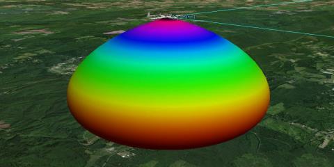
Volume Graphics
You can see that the antenna is pointing toward the ground. You need to reposition the receiver’s antenna.
Reorient the Antenna
The antenna’s elevation is 90 degrees, which points the antenna down. You need to point the antenna up.
- Return to the Receiver's () properties ().
- Select the Basic - Definition page.
- Select the Antenna tab.
- Select the Orientation tab.
- Set the Elevation to -90 deg.
- Click Apply.
- Bring the 3D Graphics window to the front.
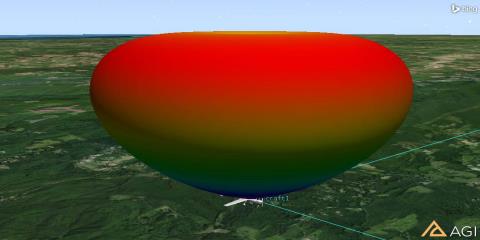
Fixed Orientation
The antenna is now properly directed toward the satellite transmitters. You can remove the volume graphics if desired.
Disable the Volume Graphics
- Return to the Receiver's () properties ().
- Browse to the 3D Graphics - Attributes page.
- In the Volume Graphics field, disable Show Volume.
- Click OK.
Determine GPS Reception
Determine the signal quality between the GPS transmitters and the aircraft receiver.
Link Budget
A simple link budget reports the values that determine the GPS reception. For the purposes of this scenario, you will focus on one column in the link budget: C/No (dB * Hz). A value of >35 means you have good GPS reception.
- In the Object Browser, right-click on GPSRcvr.
- Select Access ().
- Expand (
 ) all of the GPS satellites so that you can see the attached transmitters.
 - Using the Ctrl key, select all of the transmitters.
- Click the Link Budget... button in the report area.
- When the link budget report appears, browse to the C/No (dB * Hz) column.
- How is the reception between your GPS receiver and the satellite transmitters?
- Close the link budget report and the Access tool.
- Extend the Analysis menu and select the Remove All Accesses option.
GPS Jammer
As stated earlier, the jam team is employing an inexpensive handheld GPS jammer.
- Insert a Transmitter () object on the GPSJammer () object using the Insert Default method.
- When the Select Object window appears, select the Place object in the list and click OK.
- Rename the Transmitter object "Jammer."
Build the GPS Jammer
Most hand held jammers have similar specifications.
- Open Jammer’s () properties.
- On the Basic - Definition page, set the following options:
| Option | Value |
|---|---|
| Type | Complex Transmitter Model |
| Frequency | 1.57542 GHz |
| Power | 1 dBW |
Model the Antenna on the Jammer
The antenna on a hand held unit could be a dipole or a helix antenna. This model uses a dipole antenna.
- Click the Antenna tab.
- Set the following options:
| Option | Value |
|---|---|
| Type | Dipole |
| Length | 7.4 in |
| Efficiency | 80% |
Set the Jammer Modulation
The modulation of the GPS transmitters uses a bandwidth of 2.046 MHz. The inexpensive jammer employs a much smaller bandwidth, targeting the carrier wave. The Narrowband Uniform analytical modulator has been added specifically for modeling narrowband jammers.
- Click the Modulator tab.
- Set the Name to Narrowband Uniform.
- In the Signal Bandwidth field, disable Auto Scale.
- Set bandwidth to 25 kHz.
- Click OK.
Communication System and Interference
STK Communications provides a CommSystem object that lets you identify interference sources and calculate the impact of interference on the communications links.
To set up a CommSystem object, you must first organize the relevant communication assets into three groups:
- the transmitter(s) in the communications link of interest
- the receiver(s) in the communications link of interest
- the potentially interfering transmitter (Jammers)
- Using the Insert STK Objects tool, insert three (3) Constellation objects into the scenario using the default method.
- Rename the new Constellation objects Transmitters, Receiver and Jammer.
Transmitters Constellation
- Open Transmitters (
 ) properties ().
 - In the Selection Filter: field, enable Transmitter.
- In the Available Objects list, Move (
 ) all the transmitters to the Assigned Objects list.
 - In the Assigned Objects list, remove (
 ) Jammer. You are only interested in the GPS transmitters.
 - Click OK.
Jammer Constellation
- Open Jammer’s () properties ().
- In the Basic - Definition page, move the Transmitter object named Jammer to the Assigned Objects list.
- Click OK.
Receiver Constellation
- Open Receiver’s () properties ().
- In the Basic - Definition page, move the Receiver object named GPSRcvr to the Assigned Objects list.
- Click OK.
Build the Comm System
The CommSystem object models dynamically configured communications links between constellations of transmitters and receivers.
- Add a CommSystem (
 ) object to the scenario using the Insert Default Object tool.
 - Rename the CommSystem object Interference.
- Open Interference’s () properties ().
- Select the Basic - Transmit page.
- Move () the Transmitters constellation to the Assigned Constellation column.
- Select the Basic - Receive page.
- Move () the Receiver constellation to the Assigned Constellation column.
- Select the Basic - Interference page.
- Move () the Jammer constellation to the Assigned Constellation column.
- Browse to the Basic - Link Definition page.
- In the Constraining Constellations field, enable Transmit. You will create a custom graph. Enabling Transmit will make it easier for you to jump between the transmitters when creating your graph.
- Browse to the Basic - Interval page.
- Set the Step Size to 60 sec.
- Click OK.
If the Comm System object does not appear in the Insert Objects tool, click the Edit Preferences... button and add it.
Calculate Jamming
You are now ready to calculate jamming.
- In the object browser, right click on Interference ().
- Select CommSystem and click on Compute Data.
- When Compute Data is complete (there is a progress bar in the lower right corner of STK), right click on Interference.
- Select Report & Graph Manager.
Custom Graph Design
The Link Information Detailed report will give you the desired comparison between a normal reception and an interfered with reception (C/No (dB*Hz) versus C/(No+Io) (dB*Hz)). You can create a custom graph that compares both of these values over time. This can make it easier to quickly determine how effective the small jamming device is working.
- In the Styles field, disable Show Reports and enable Show Graphs.
- Right click on the GPSJamming Styles folder, select New and click Graph.
- Rename the new graph style "Jam Test".
- Click the Enter key on your keyboard which opens Jam Test's properties.
- If required, expand the Link Information data providers list.
- Locate C/No and move it to the Y Axis field.
- Locate C(No+Io) and move it to the Y Axis field.
Match the Report Units
You want to match your bandwidth units to the units you originally saw in the Link Budget report you created earlier in the scenario. In the report, Hertz was used, but the default units in the graph are Megahertz.
- Select Link Information - C/No in the Y Axis contents list.
- Click the Units... button.
- Disable the Use Defaults option.
- Select the Bandwidth Dimension option.
- Select Hertz (Hz) in the New Unit Value field.
- Click OK.
- Repeat the steps above for Link Information - C/(No + Io).
- Click Apply
Change the Graph Layout
It will be easier to view the graph by darkening horizontal graph lines.
- Browse to the Layout page.
- In the Grid Lines field, enable Horizontal Grid Lines.
- Click OK.
Generate a Graph
- In the styles field, highlight Jam Test and click the Generate button.
- When the Assigned Object pop-up window appears, move one of the transmitters to the Assigned Objects list and click OK.
- If desired, close your graph and return to the Report & Graph Manager.
- You can generate another graph using a different transmitter by following steps 1 and 2.
You can select multiple transmitters at the same time, but the graph might be difficult to read.
By looking at the graph, you can quickly ascertain when your receiver's reception of the GPS signal is dipping below thirty-five (35). When this happens, that signal is effectively jammed.
This technique is a simple way to walk through the list of transmitters to see if each transmitter is affected by the jammer and when the jamming takes place.
Generate a Report
You can view all the transmitters on one report.
- Return to the Report & Graph Manager.
- In the Styles field, turn Show Reports on and Show Graphs off.
- Select Link Information Detailed and click Generate.
- When the Assigned Objects window appears, select all the transmitters in the Available Objects field and move them to the Assigned Objects field.
- Click OK.
- When the report appears, scroll to the right and locate the C/No (dB*Hz) and C/(No+Io) (dB*Hz) columns.
- Scroll down through the report to see how the hand held jamming device is affecting the aircraft's GPS reception.
Save your work.
 Visit AGI.com