Movie Making Tutorial: Behind The Scenes
STK provides the capability to either save a collection of still frames from the 2D or 3D window, and compile them into a movie with third party software, or save a ready-to-play movie directly from STK. Movie making can be divided into three parts:
This tutorial covers preparation, camera control, and rendering content. In an ideal world you would prepare your scene before positioning the camera, but sometimes you don’t realize something needs to be added, removed, or changed until after the camera has been positioned. So, in a real situation, you may find yourself switching back and forth between the first two steps.
A movie, for the purpose of this discussion, is a single scene of continuous motion. A movie may run from a few seconds to a few minutes, depending on your requirements. Movies tell a story. The story can be about something that has happened, might happen, or something that is happening right now. Scenarios in STK do the same thing, but often cover a much larger area in both time and space than a single movie can convey. This tutorial assumes that your scenario is technically complete. Preparing the scene, which comes next, is what you do to make it movie ready.
Preparing the Scene
Engineers, as a rule, focus on technical accuracy more than aesthetics. If your audience is largely non-technical, aesthetics may be a powerful influence. The one question that you never want to hear is, "What was that?" Asking, "What was that?" means that the movie has failed, in one way or another, to tell the intended story. There are three areas that comprise scene preparation:
Lighting
Lighting parameters can be found on the 3D Graphics - Lighting page. A complete description of the lighting panel can be found here. STK's default lighting source is the Sun. To ensure good contrast, set the Sun Lighting as follows:
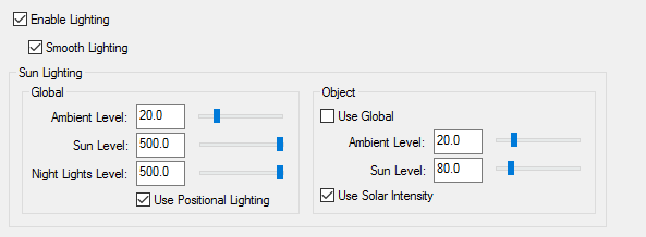
Sun Lighting
There are two settings for Sun Lighting, Global and Object. Global Lighting only affects how of your central body is lit. Object Lighting only affects objects that are part of your scenario. This includes clouds and sensors.
The Ambient Level determines how bright the darkest parts of your globe or objects will be lit. To increase contrast, lower the Ambient Level while increasing the Sun Level. Maximizing Global Sun and Night Lights levels (set it to 500) optimizes the sharpness of the solar terminator,
Under Object, the Ambient Level plus Sun Level should always equal 100. If it does not, objects in your scenario will appear either overexposed or underexposed.
Flashlight
What if your movie starts out on the dark side of the Earth? Try not to let this happen. If your movie must start on the dark side, STK allows you to add additional lighting sources. A less precise, but much faster, solution is to use the flashlight.
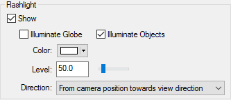
You have control of the brightness (Level), Color and which way the Flashlight is pointing (Direction). The flashlight can illuminate the central body, objects in the 3D window, or both. Remember that all lighting is additive. Objects lit by the Sun will most likely be over exposed if the flashlight is also enabled.
Rendered video is never as clear as the source from which it is made. So if it’s a little hard to see in the scenario, it will be all but invisible in a video. Thin or dark colored labels and lines, for example, are really hard to see on the black background of space. Change them.
Framing
Framing has to do with the shape and size of your video and the volume of space it contains. Framing can be divided into two parts, screen size and field of view.
Screen Size
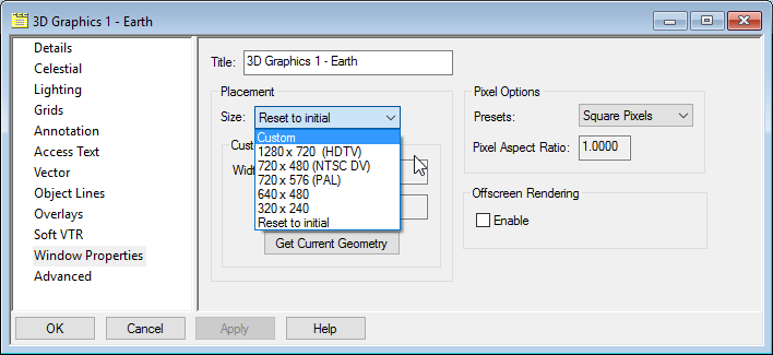
Screen size is found on the 3D Graphics - Window Properties page. You can choose one of the predefined window sizes, from the pull-down, or you can define a custom window size. For desktop presentations, we recommend using 1280 x 720.
Field of View
Field of View is found on the 3D Graphics - Advanced page. STK's default value for field of view is 45 degrees. A square 3D Graphics window will have the same field of view in both directions. If your 3D Graphics window is 1280 pixels wide and 720 pixels high, only the largest dimension, in this case 1280, will match the field of view setting.

As your field of view gets wider, the objects in your 3D window get smaller; but you will also see more of them. You may also notice a bit of distortion in the corners of your 3D window when the field of view is greater than 60 degrees.
Avoid changing your window size or field of view after making a camera path. If either of these is changed, elements may be cropped out of, or unwanted elements added to, your 3D window. If your window size or field of view do change, review your camera path and make the necessary changes.
Visual Elements
Visual elements of a movie include models, textures and terrain. Some elements may move and change, others won't. Visual elements may have little to do with the technical nature of your scenario, but often add credibility to the technical parts that are already there. Depending on their size and frequency of use, some of these may impact performance.
Adjust Settings to Improve Performance
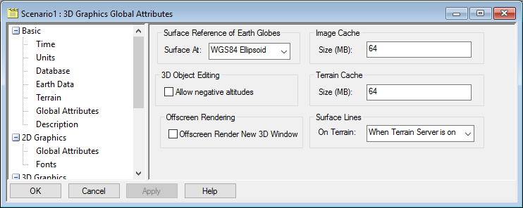
STK allows global textures and terrain to be stored in RAM rather than your hard drive to improve performance. Under the Scenario Properties on the 3D Graphics - Global Attributes page, the settings for Image Cache and Terrain Cache let you specify the amount of system RAM to be set aside for this. This RAM will only be used if it is needed, and is done on a per scenario basis. If you experience the 3D window refreshing slowly, blurred textures, or artefacts in the 3D window, you may need to increase the size of your Cache.
On a PC with 32 GB of RAM, we suggest increasing the Image Cache to 1024 mb and the Terrain Cache to 512 mb.
Increasing these settings can only improve performance if your scenario contains an equivalent amount of textures and terrain.
Space-based Scenarios
For space-based scenarios, you can change the stars to display as points OR textures on the 3D Graphics - Celestial page.
It is possible to display stars as both Celestial imagery and points at the same time, but it is not advised.
When you display stars as points, you have control over the size and color of the points, and the magnitude they represent. The values shown below are optimal in most cases. If you want a photorealistic night sky, you can show the sky as a sky texture. AGI has acquired the rights to use Axel Mellinger's Milky Way Panorama imagery for use in STK. This imagery was assembled from hundreds of photographs showing nebulae and galaxies, not just stars. It is freely available to all STK users and can be found here.
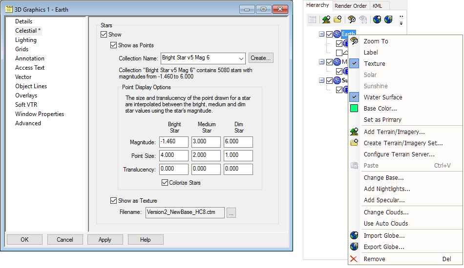
Add Textures Through Globe Manager
To enhance your 3D Graphics window, you can add a high resolution Nightlights texture, animated water surfaces, a global specular highlight, and world cloud textures. Some of these visual elements are included in the STK install and the rest are on the supplementary data disk. Additional textures, not found on the install or supplementary disks, can be found here.
Enhance Labels and Annotations
Here are a few suggestions to improve the appearance of labels, annotations and lines:
- Labels and annotations look best in plain thick font. Thin or small font is difficult to read in a video.
- The same rule also applies to orbit lines, vehicle tracks and annotation lines.
- Access lines, unfortunately, can only be one pixel wide.
- Fonts are selected under the Scenario Properties in the 3D Graphics - Fonts page, shown below.
There is a similar property on the 2D Graphics page that looks identical. These properties are, however, independent.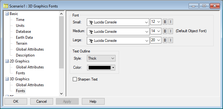
Dynamic Visual Elements
The first time I made a launch movie I was disappointed to learn that my launch vehicles didn’t come into existence until the moment of launch. That meant there was nothing to look at until liftoff. To compensate for this, I created a new facility at the same location as the launch vehicle and used the same model. Such a “vehicle” only needs to be seen before launch. To make it disappear at launch, do the following:
- Open the facility 2D Graphics - Display Times page.
- Enable the Use Intervals option.
- Create a Start/Stop interval where the stop time is the moment the launch vehicle comes into existence.
At launch time, both objects are visible. To align them, adjust the Facility properties’ 3D Graphics - Offset values. The same thing can be done using Articulations under the Facility properties 3D Graphics- Model page in the Articulations - View dialog. Once aligned, change the 2D Graphics - Display Times - Stop Time to be one time step before liftoff. When playing the scenario, the launch vehicle can be seen sitting on the pad for a period of time before liftoff.
Other visual elements you may wish to consider are the use of vapor trails, the addition of tick marks on satellite objects, and writing articulation scripts, found here. Articulation scripts control the behavior of model parts such as exhaust flames, landing gear, and munitions deployment.
Controlling The Camera
Here we will begin making a camera path. Open the Camera Control window, shown below. You will see three tabs, but for now, we will only be focused on one, the Keyframes tab. The upper dialog lists your Camera Paths while the lower dialog lists the keyframes of the highlighted Camera Path.
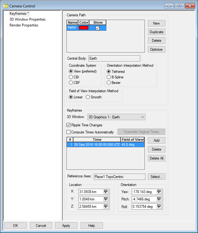
Coordinate System
The Coordinate System you select displays the camera’s frame of reference in the Location and Orientation dialogs at the bottom of this page. There are three options:
- View (preferred)
- CBI (Central Body Inertial)
- CBF (Central Body Fixed)
The X, Y, and Z values of Location and the Yaw, Pitch and Roll values of Orientation, at the bottom of this page, displays the highlighted keyframe in that coordinate system. Selecting a different Coordinate System will not alter a keyframe. A keyframe can only change if you first edit these fields and then click Add.
Orientation Interpolation Method
Orientation Interpolation Method controls the shape of your camera path. There are three options:
- Tethered
- B-Spline
- Bezier
In Tethered mode the camera passes through each point on the curve. Think of it as a very tight fit. Bezier, on the other hand is a very loose fit making the curve smoother.
In Bezier the camera does not pass through the exact point you selected. B-Spline is somewhere in between. The camera comes closer to the point you selected, but may not hit it exactly. B-Spline is tighter than Bezier, but looser than Tethered. If your camera path is only two points, none of this will matter. Your camera path will always be a straight line.
In most cases, you will keep the same Field of View throughout your movie. If you have a need to change it, Field of View Interpolation Method gives the camera two ways to behave. Linear changes the Field of View from one keyframe to the next at the same rate for each time step. Smooth changes the field of view at a variable rate.
It is important to know that you can change any of these parameters after making a camera path and the keyframes will not be affected. These parameters only determine the shape of the curve that fits around the keyframes.
It is advisable to set the start and stop time of your scenario to the start and stop time of your movie. Begin building your camera path by clicking New in the Camera Path dialog. The opening scene of your movie familiarizes viewers with the context of your scenario. It is called an establishing shot. For this keyframe, you almost always want to position the camera some distance away with the significant action at, or near, the center of your frame.
Clicking the Add button, in the Keyframes dialog, stores the position, orientation, and field of view of your keyframe. This button is used to create new keyframes and edit old keyframes. Clicking the Add button also increments the clock one time step.
Here’s a neat trick. Set the time step of the scenario to the desired interval between keyframes. That way you can build a camera path very quickly. Just click Add, move the camera to its new position, and click Add again.
Rendering Content
Rendering is the final step in making a movie. In this section, it is assumed that you have already created a scenario with desirable lighting, visual elements, and a camera path.
The Recording of movie content is controlled by the 3D Graphics/Soft VTR panel, shown below. Before you do anything in Soft VTR, make sure you are using the desired camera path and that it is active. To activate your camera path, click this button  on the Camera Control toolbar. You should now see a box around this button. As you play your scenario, the camera will follow your path. To deactivate your camera path, click the button again or just click and drag anywhere in the 3D window.
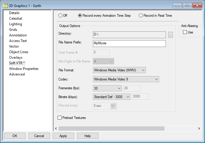
When you first open SoftVTR, the Off radio button will be active. Recording is disabled. Even if you save your scenario with one of the Record buttons active, your scenario will always be saved with the Off button active. After clicking Apply, every frame that appears in your 3D window will be saved to your hard drive. This will continue until you select Off and click Apply.
Once Soft VTR is set to record, Click  (Start) on the animation toolbar. STK will begin writing either still frames or compile a movie file to your hard drive. It does not control the camera. Soft VTR will record the 3D Window even If no camera path is activated. Recording will continue until you reach the Stop Time of your scenario, or you press
  (Pause). You must then select Off and click Apply in SoftVTR. This is the only way to stop recording. For more information, see Soft VTR properties for the 3D window.
Summary, Tips, and Techniques
There are many ways to go about making a great camera path but nearly all of them share certain characteristics.
Avoid Crowds
Make sure each keyframe evenly fills the 3D Graphics window, but does not over crowd it. Avoid bunching relevant action into one area leaving wasted space elsewhere. This happens a lot with object labels. Remove any non-essential labels. Labels must always be readable.
Stay Focused
Keep relevant action near the center of the frame. If relevant action does go out of frame, reposition the camera and make a new keyframe at that time.
Keep Moving
Once the camera is moving in a given direction, keep it moving in that direction. Do not suddenly stop, and move in the opposite direction. This conveys confusion and a lack of confidence to the viewer. Home movies are famous for this. Don’t make the camera look like it’s attached to a windshield wiper. If you must move in the opposite direction, do so in a circular motion. Start moving diagonally, then at a right angle, opposite diagonal, and finally opposite. Think of the camera as an ice skater.
Mind the Gap
Keep your keyframes evenly spaced. Anytime there is a sudden or large change in camera location or direction, you will experience unpredictable camera motion between keyframes. If you’re lucky, that may work for you. Luck is not a repeatable strategy.
Cheating is Allowed
Any camera path with only two points will result in a straight line. To force a multi-point splined camera path to make straight lines, capture two identical points less than one time step apart. The earlier portion of the spline will end in a straight line and a new spline will begin. This is often the solution to the "ringing" artefact you get when the camera path experiences a sudden change in speed or direction.
Don’t Try Too Hard
If your camera path looks chaotic or, for any reason, you do not have the beginnings of a reasonable camera path after 10 or 15 minutes, start over. Most of the time it will take you less time to make a new one from scratch, than to correct multiple mistakes in your current camera path.
Less is More
The fewer keyframes you have, the smoother your camera path will be. Each keyframe produces a change in the spline. If you have too many keyframes, the path will appear bumpy. Delete keyframes that don't contribute.
Experiment
If you're not sure, or a camera path is almost right and you think you can add or remove a point without changing the good parts you already have, make a duplicate of your camera path and make your changes there. If it works, delete the original. If it doesn't, delete the copy and try again.
 Visit AGI.com