This tutorial will familiarize you with importing terrain and imagery for visualization in STK. In this tutorial, you will use STK image and terrain converters to generate STK visualization files and display them in both 2D and 3D Graphics windows.
STK Professional.
The results of the tutorial may vary depending on the user settings and data enabled (online operations, terrain server, dynamic Earth data, etc.). It is acceptable to have different results.
You will learn:
- The STK terrain and imagery data formats
- How to introduce terrain or elevation data to the STK Scenario
- How to use the Imagery and Terrain Converter
- How to use the Color Elevation Imagery tool
- How to load image inlays to both 2D and 3D Graphics windows
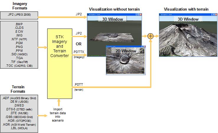
To accommodate 3D rendering performance in a dynamic window, STK requires data formats that are optimized for speed and streaming. STK utilizes proprietary formats and an open format (JPEG 2000) to accomplish this and offers a conversion tool to allow a wider range of geospatial data to import into STK.
STK imagery visualization formats
| Option | Description |
|---|---|
 .PDTTX .PDTTX |
AGI proprietary format for 3D and 2D Graphics windows |
|
JP2 (JPEG 2000) |
Non-proprietary format for 3D and 2D Graphics windows |
| Option | Description |
|---|---|
 .PDTT .PDTT |
AGI proprietary format for 3D Graphics windows |
Create a Scenario:
- Open STK and click the Create a New Scenario button.
- Enter the following in the New Scenario Wizard:
- When you finish, click OK.
- When the scenario loads, click Save (
 ). A folder with the same name as your scenario is created for you in the location specified above. This will ensure you do not accidentally overwrite your previous work.
 - Verify the scenario name and location and click Save.
- Close the Insert STK Objects tool (
 ).
).
| Option | Value |
|---|---|
| Name | Mountain |
| Location | C:\Documents and Settings\<user>\My Documents\STK 11 (x64)\ |
| Start | Accept default start time |
| End | Accept default end time |
Importing Terrain Data to a Scenario
In this exercise, you will attach terrain data to your scenario, which will be utilized in several of the exercises in this tutorial.
- Open the scenario Properties Browser and select Basic – Terrain.
- Disable the Terrain Server option.
- Right-click on the scenario (
 ) and open the Properties (
 ).
). - Select the Basic - Terrain page.
- Disable the Use terrain for analysis option.
- Click OK to apply changes and dismiss the Properties Browser.
- Right-click on the scenario (
- Click the Add button and in the Open dialog boxselect USGS DEM (DEM) in the file type drop down.
- Browse to the file hoquiam-e.dem in <STK Install Dir>/Help/stktraining/samples and click Open.
- Click OK to apply changes and dismiss the Properties Browser.
- Save () your scenario.
Your terrain data is now in your scenario and can be used for analysis. However, you would like to visually see it with draped imagery. Let’s see how that can be done.
Using the Imagery and Terrain Converter
The Imagery and Terrain Converter can be used to convert terrain and imagery content for 2D and 3D visualization. If your imagery is already in a native format, such as JPEG 2000, conversion is not necessary. (See Appendix A.) An image of St. Helens is used to drape over the terrain (image is courtesy of Space Imaging, Inc.).
Creating a 3D Image Inlay
In this exercise, you will utilize the Imagery and Terrain Converter to create two inlays for the 3D Graphics window that will display a photographic image of St. Helens.
- Click the Utilities menu and select Imagery and Terrain Converter…
- Select the Single Image page.
- Click the ellipsis button next to the Image Filename: field.
- Browse to the <STK Install Dir>/Help/stktraining/samples, select the SpaceImaging St Helens.sid file and click Open.
- Click Convert.
Notice that in the Extent area, the Image extent fields are automatically completed once you open the SpaceImaging St Helens.sid image file. This is because the file contains georeferencing data that STK can read. For some types of image files—those that do not contain georeferencing data—you will have to enter the image extents manually.
Convert a DEM to JP2
Now that you have converted an *.sid file, try to convert a *.dem file.
- In the Input Data Terrain section, select Use.
- Select the hoquiam-e.dem terrain data—which will be displayed with its path name—from the drop-down menu.
- In the Output Data section, ensure JPEG 2000 (jp2) is selected from the drop-down list in the Image File Format: field.
- Set the Compression Ratio to 10.
- Set the Image File Directory to your scenario folder.
- Click Convert.
- Click OK.
You may have to scroll down in the Imagery and Terrain Converter in order to see the Convert button. The conversion for the terrain and imagery will now happen. Please wait until the conversion is done.
View the Terrain in 3D
- Select SpaceImaging St Helens.jp2 and SpaceImaging St Helens.pdtt.
- Click Open and your .jp2 and .pdtt will be available in your Globe Manager. If the “Use Terrain for Analysis” window appears, click No.
- Select SpaceImaging St Helens.jp2 in the Globe Manager. Click on the Zoom To (
 ) button in the Globe Manager toolbar. This will take you directly to the image on the 3D Graphics window.
Disable and Enable the Extents
In one action we converted an image (.pdttx) and terrain (.pdtt) with the same extents.
- In the Globe Manager experiment with disabling or enabling them.
What if you don't have an image and you just want a terrain file (.pdtt)? Under Image Converter -> Terrain Region you can select scenario terrain sources from the drop down and covert them as a whole or subsets.
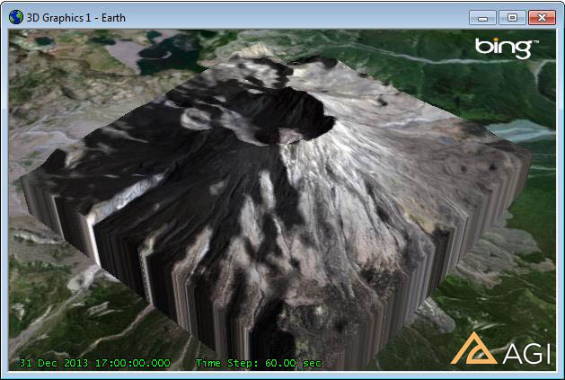
3D View: Mt. St. Helens
Displaying Your Image Inlay in 2D
- Open the 2D Graphics window properties browser () and select the Imagery page.
- Click Add… and verify that the file type is set to All Supported Types.
- Browse to your scenario folder or the location where you saved the file, select SpaceImaging St Helens.jp2 and click Open.
- Verify that Show is selected.
- Enable the Show Image Extents option.
- Select SpaceImaging St Helens.jp2 and click the Zoom To () icon to zoom in on the image in the 2D Graphics Window.
- Click OK to apply changes and dismiss the Properties Browser.
- You can zoom out a bit in the 2D Graphics Window using the mouse scroll wheel. This will allow you to see the extents of the image inlay.
If you do not have a 2D Graphics window already, go to the View menu and select New 2D Graphics Window.
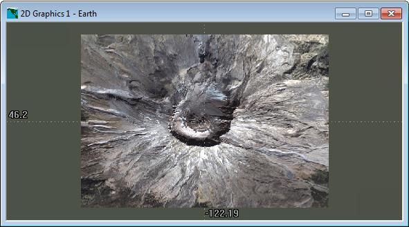
2D View: Mt. St. Helens
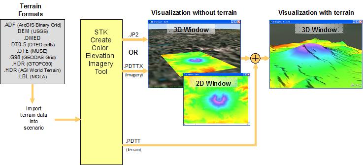
Creating Color Elevation Imagery
You can use the Create Color Elevation Imagery tool to generate images with topographically derived colors (See Appendix B):
- From the previous steps, the 2D Graphics Window should be zoomed in on St, Helens. If not, zoom in on St. Helens.
- Click the Utilities menu and select Create Color Elevation Imagery…
- Ensure the Select On 2D Map option is enabled.
- Using the cursor, draw out a rectangle around St. Helens. You will notice that the terrain region coordinates will update in the Create Color Elevation Imagery window.
- Return to the Create Color Elevation Imagery window and in the Output File area, ensure JPEG 2000 Image (.jp2) is selected as the Output File Format.
- In the Directory field, click the ellipsis button, navigate to your scenario folder and click OK..
- Enter St Helens Topo in the Filename field.
- Click Convert.
- Close the Create Color Elevation Imagery window.
- On the 3D Graphics window toolbar, select the Globe Manager (
 ) and click the Add Terrain/Imagery (
 ) button.
 - Browse to your scenario folder or the location where you saved the file and select St Helens Topo.jp2.
- Click Open.
Do not select Create a pdtt file for the selected region. You already made one in the previous exercise.
You will see your topographical inlay in the 3D Graphics Window.
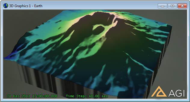
3D View: Color shading based on terrain height
Adding To the 2D Graphics Window
- Open the Properties Browser () for the 2D Graphics window and select the Imagery page.
- Click Add…, and verify that the file type is set to All Supported Types.
- Browse to your scenario folder or the location where you saved the file and select St Helens Topo.jp2.
- Click Open.
- Click OK to apply changes and dismiss the 2D Graphics Properties. Your topographical inlay will now be visible in the 2D Graphics window.
- Save your scenario if you want to keep changes.
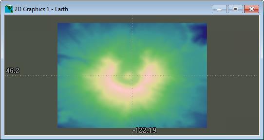
2D View: Color shading based on terrain height
Conclusion
This tutorial provided a basic overview of the Imagery and Terrain Converter and the Create Color Elevation Imagery tool. The example input imagery provided could also be used directly with JPEG 2000. STK also offers command line versions that are license-free (the exception is generating JPEG 2000 files for images over 500 MB large) for batch conversions.
Lastly, if you want to store your globe or share your globe with another user, you can export a globe file (.GLB). Previously a globe file was an essential part of a scenario, in STK 9 and higher, the globe file is only necessary for importing and exporting globes.
Appendix A - Workflow for STK Imagery and Terrain Converter
Appendix B - Workflow for STK Create Color Elevation Imagery Tool
 Visit AGI.com