EOIR Shape Properties
A missile may change shape as it moves from one stage to the next. (For example, the shape of a missile when launched is different than its shape after the first component separates from it.) Each STK Missile object represents one stage of a missile. The Basic EOIR Shape properties enables you to define the shape of a particular STK Missile by stacking components. For an example of how to stack components, see Building a Missile Shape Example.
Defining a Multi-Stage Missile
You need to create one missile object for each missile stage. When defining a stage for a multi-stage missile, keep in mind the following:
- The shape properties must match the missile stage.
- The Start and Stop times must match the time interval appropriate for the stage.
- The Missile object must be included as a selected target in the EOIR Configuration.
EOIR Shape Properties
Select or specify the following for each shape composing a stage.
Shape
Object shape can be:
- One of the simple geometrics: Box, Cone, Coupler (cone frustum), Cylinder, Plate or Sphere.
- None: Removes it from the geometric and radiometric calculations while retaining its position and orientation calculations. It is often convenient to assign the parent object to which a sensor is attached as shape None. Since a sensor cannot currently image its parent object, this speeds up radiometric calculation with little or no effect on the results.
- CustomMesh: Loads an external model (.obj) file that defines a custom model. The sample_custom_mesh.obj file loads by default. To select a different file, click the browse button. For information on converting a model file to an OBJ file, see Converting 3D Models to OBJ Files for Rendering in EOIR.
Dimensions
The dimensions (e.g., Height, Radius, Width, Depth, Max Dimension) of the simple geometric shape.
Body Temperature
Body temperature can be:
- Static. Body temperature is applied to the entire shape.
- Time Profile.Loads a time-temperature profile (.tpf) file. The sample_time_profile.tpf file loads by default. To select a different file, click the browse button. To create a TPF external file, see TPF data file format.
Material
The material type that appears on the surface of the entire shape. You can select one of the materials in the drop-down list or a Custom Material.
The Custom Material option enables you to load an external Spectral Response Function (.srf) file that defines custom materials. This file models operationally relevant materials and accurately characterizes their desired spectral response function. The sample_material_profile.srf file loads by default. To select a different file, click the browse button. To create an SRF external file, see SRF data file format.
Each Surface Material has optical properties used in the sensor scene calculation. One of these is reflectance. Light bouncing off a surface is selectively reflected by wavelength; i.e., some wavelengths are absorbed instead of reflected. In the visible wavelengths, this is what gives objects color. Each Surface Material has a table of its Reflectance versus Wavelength.
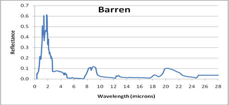
One particular material, Gray Body, has a user-selectable reflectance that is constant across the spectrum. It does not represent any real material but is useful for setting up test situations.
For more information on material models, see Material Types Modeled in EOIR.
Reflectance
The Reflectance can vary from no light reflected (0 %) to all light is reflected (100 %). Not valid for the Custom Material option.
Building a Missile Shape Example
The following example shows how to stack components to build a missile shape:
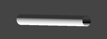
- To define the following initial component, highlight Component 1, select Cylinder as the shape, and modify the following properties:
- Height: 10 m
- Radius: 0.5 m
- Body Temperature: 310 K
- Material: White Thermal Control
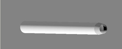
- To stack a coupler on the cylinder shape, click the Add button, highlight Component 2, select Coupler as the shape, and modify the following properties:
- Radius1: 0.5 m
- Height: 0.6 m
- Radius2: 0.4 m
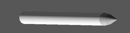
- To stack a cone on the coupler shape, click the Add button, highlight Component 3, select Cone as the shape, and modify the following properties:
- Height: 1 m
- Radius: 0.4 m
Note that Radius1 is set to match the Radius of the Cylinder shape.
The following image shows how the coupler is stacked on top of the cylinder.
The following image represents the finished missile shape.
 Visit AGI.com