STK Analysis Workbench Tools
Introduction
The Time, Vector Geometry, and Calculation Tools, collectively known as the STK Analysis Workbench Tools ( ), are application-wide tools designed to streamline, organize, and extend the fundamental computational capabilities of STK.
| STK Analysis Workbench Tools | |
|---|---|
| Tool | Description |
| Time Tool | Creates components that produce instances or intervals of time. |
| Vector Geometry Tool | Creates components that define location, pointing, and orientation in 3D space. |
| Calculation Tool | Creates components that produce various time-dependent quantities. |
| Spatial Analysis Tool | The Spatial Analysis tool enables you to create calculations and conditions that depend on locations in 3D space which are, in turn, provided by user-definable volume grids. |
The tools are comprised of several types of components:
Users can select from a large number of installed components or create components that suit their needs. In many cases, users can create custom computational flows by using the results produced by some components as inputs for other components.
Any of the installed or user-created components can be used to report, graph, create data files, and visualize 2D and 3D time-dynamic data. They can also be accessed via the STK Connect interface, the STK Object Model interface, and the STK scripting interface which supports Perl, VB Script or MATLAB.
Each type of component is uniquely defined by the type of its output. For example, all components of Interval List type produce ordered intervals of time. In addition to producing intervals, components of this type can also determine if an input time falls within any of these intervals.
There may be (and usually are) several methods by which a component of a particular type can be created. For example, a component of Interval List type can be created from a set of interval data specified in an external file. Also, one can be created by merging intervals from two other Interval List components as prescribed by various logical operations such as AND, OR, XOR, MINUS. Or one can be created by time shifting another interval list.
The important paradigm in this design is that, while there may be many methods for creating components of a particular type, all components of the same type must support the same type of output. This kind of standardization facilitates and promotes a modular approach to computations.
Users can (and are guided to) design their computational tasks by combining different types of components from the Time, Calculation, and Vector Geometry tools. The end products are computations and geometric constructs that are displayed in reports and graphs, stored in files, and depicted in 2D and 3D displays.
Some of these tasks may become very complex and involve various combinations of a large number of components. However, because of standardization, any one component can be replaced by another of the same type without affecting the rest of the computational flow.
Also, even if users are ultimately interested in the end products, they can always examine and debug any of the intermediate computations and geometric constructs.
General Tool Enhancements
All components in the Time, Calculation, Vector Geometry and Volumetric tools appear in the same window (Figure 1).
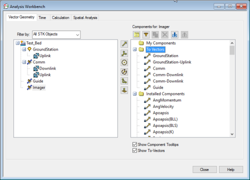
Figure 1: Analysis Workbench window with the Vector Geometry Tool tab selected.
The object tree is located on the left side of the browser.
Using the Filter by: drop-down list (Figure 2) the object tree can be set to display all STK Objects or only STK Objects of a particular class.
Figure 2: Filter the types of objects or classes of objects displayed in the object tree using the Filter by: drop-down list.
Alternatively, the tree can be set to display either Primary or Secondary Central bodies or it can be set to display both STK Objects and Central bodies.
Finally, it can be set to display classes of STK Objects for template components, which when defined for a class of objects, will appear for every object instance of the class. Template components can be constructed from other template components of the same class, Central Body components, or object components. If object components are selected, the template is only valid if the specified object is in the Scenario.
In all cases, components appear in the tree on the right. Components of different types appear in the tree using different icons. Installed components are placed in the Installed Components folder. User-defined components are placed in the My Components folder.
| Component Actions | |
|---|---|
| Icon | Description |
|
|
Create new components. Component types that are not available for a specific object will be grayed out. |
|
|
Duplicate the selected component. |
|
|
Examine or edit the selected component. |
|
|
Delete the selected components. |
|
|
Filter components of a specific type from the tree. |

|
Import a component from a file. A file with the same name as an existing component will not be imported. |

|
Export a component to a file. Components that are not duplicable cannot be exported. This includes File and Custom Script components. |
Multi-line tooltips appear whenever a mouse is over a component in the tree. The tooltips can be turned off by clearing the Show Component Tooltips check box. Tooltip display can be managed by specific tool or panel in the Analysis Workbench preferences window.
Components can be renamed either in the tree or by opening the edit panel that contains component name, type, description, parent object, and all of the relevant definitional information. In the tree, the right-click menu also provides options to duplicate or delete an existing component.
To duplicate a component, select the desired component and click Duplicate Component (![]() ). The copy will appear in alphabetical order in the My Components section of the component tree.
). The copy will appear in alphabetical order in the My Components section of the component tree.
When duplicating components, if the component name is greater than 61 characters, it will be truncated to 61 characters to allow for the addition of a number (up to 3 digits) to make the name unique.
Dependency Tree
In addition, the right-click menu provides options to examine dependencies of the selected component which opens a new panel with another tree that contains all components that depend on the selected component or alternatively all constituent components on which the selected component depends.
Note that this dependency tree appears whenever an existing component is about to be deleted. Users are then given the opportunity to examine the effect of the removal before confirming or canceling the operation.
Additional Options
In addition to the dependency view, the right-click menu provides options that are specific to each component type.
Reporting Options for Time and Calculation Components
All components from Time and Calculation Tools have on-the-spot, right-click, reporting options that enable you to generate reports and graphs using all of the relevant information from the selected component without first having to create a new style. Time and Calculation reports and graphs include the object name and Time/Calculation Component Name in the title.
Access Components
A set of components is automatically created for all access objects. See the Access Components page for more information on how they may effect reporting and graphing.
Getting Started
Click one of the following tutorials to begin.