Basic Constraints
Basic Constraints enable you to impose standard access constraints on an object. You can also opt to exclude time intervals that satisfy a given constraint.
If a constraint is not available for accesses from an object, it will be disabled (grayed out) in the Constraints properties page for that object. The table below describes the basic constraints and lists the objects that they can be used to constrain access to.
In the following table, abbreviations in the Constraints used for accesses to... column are:
| F = facility | Pl = place | T = target | V = all vehicles | S = satellite | M = missile | L = launch vehicle |
| A = aircraft | Sh = ship | Sn = sensor | AT = area target | P = planet | St = star |
| Constraint | Description | Constraint used for accesses to... |
|---|---|---|
| Azimuth Angle | For facilities and targets, azimuth is measured in the local horizontal plane, tangent to the surface of the central body. This angle is measured from the local north direction towards the local east direction. An azimuth of 0 degrees specifies a location directly to the north and an azimuth of 180 degrees specifies a location directly to the south. For ships, ground vehicles and aircraft the azimuth is measured from the projection of the earth fixed velocity vector. In the case where the vehicle is stationary, azimuth is measured from local north in the topocentric frame. For other objects, azimuth is measured in the plane perpendicular to nadir from the projection of the inertial velocity vector to the projection of the relative position vector. This angle is measured in a positive sense according to the right-hand rule about the nadir vector. An azimuth of 0 degrees specifies a location directly in front of the object and an azimuth of 180 degrees specifies a location directly behind the object. |
F Pl T P St V |
| Azimuth Rate | The azimuth rate is the rate of change of the azimuth angle. | F Pl T P St |
| Angular Rate | The angular rate is the rotational rate of one object, which is necessary to keep a fixed vector in that object's body-fixed coordinate system aligned with the line of sight between the two objects. | F Pl T P St V |
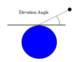
| Elevation Angle | For objects other than facilities and targets, elevation is measured as the angle between the nadir vector and the relative position vector minus 90 degrees. The elevation angle is positive for objects above the plane perpendicular to nadir. For facilities and targets, elevation is measured as the angle above the local horizontal plane where the local horizontal plane is tangent to the surface of the central body. The elevation angle is positive for objects above the local horizontal plane. |
F Pl T P St V |
|
Elevation Angle constraint as applied to a satellite
Elevation Angle as defined for a facility or target
|
||
| Elevation Rate | The elevation rate is the rate of change of the elevation angle. | F Pl T P St |
| Altitude | Access to the object is constrained by minimum and maximum altitude of the object to which the constraint is applied. In cases in which ships or ground vehicles have a constant altitude that is near or equal to the minimum altitude constraint, numerical noise may determine access times and yield no access. In these circumstances it is recommended that the minimum altitude value be set to just under the desired constraint, e.g. for a desired minimum constraint of 50m set the minimum altitude to 49.99m, so that the object will show access when at the exact desired minimum constraint altitude. |
All |
| Range | The range is measured as the distance between the two objects. | F Pl T V |
| Range Rate | Range rate is the component of the relative velocity along the line of sight of the two objects. | F Pl T V |
| Propagation Delay | Access to the object is constrained by the minimum and maximum time it takes the signal to travel between the two objects. | F Pl T V |
| Line of Sight |
If this option is checked, access to the object is limited to lines of sight not obstructed by the ground. A vehicle models the ground as the ellipsoid shape defined by its central body. A star or planet models the ground as the ellipsoid shape defined by the other object's central body unless the other object is a facility, place, or target. If the other object is a facility, place, or target, then its ground modeling method is used (whether or not the Line of Sight option has been selected for it). In addition, a planet is modeled as its center point. If the planet's central body is the same as the central body of the other object in the access computation, and Default is selected as the planet's Ephemeris Source, then the planet's line of sight is not obstructed by the planet's surface. A line target or area target evaluates the Line of Sight constraint on each of its edge points; an edge point is considered unobstructed by the ground if its elevation to the other object is greater than 0 degrees. A facility, place, or target models the ground as the ellipsoid
passing through its ground position with the same surface normal
vector as that of its central body ellipsoid shape. A facility, place, or
target configured with non-zero height above ground may look downward
from that height to its ground model. When a transmitter is parented by a sensor with the LOS constraint enabled, the transmitter's link Information values will be constrained within the sensor geometric field of view. See below for more on the Line of Sight constraint. |
F Pl T P St V |
|
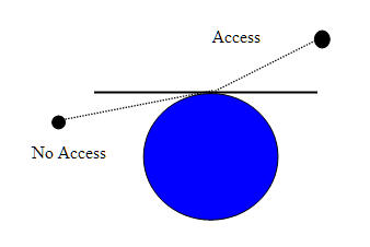
Line of Sight constraint as applied to satellites
Line of Sight constraint as applied to a facility, ground vehicle, ship, or target
|
||
| Terrain Mask | If this option is checked, access to the object is constrained by any terrain data in the line of sight to which access is being calculated. See comparison with AzEl Mask. | F Pl T P St V |
| AzEl Mask | If this option is checked, access to the object is constrained by azimuth-elevation masking. The mask used can come from terrain or a custom az-el mask as defined in the basic properties of the facility, place or target. See comparison with Terrain Mask. | F Pl T V P |
| Field of View | (Sensors only) If this option is checked, access is denied if the associated object is not within the field of view as defined by the angle settings for the sensor type in question. | All |
| Sensor AzEl Mask | (Sensors only) If this option is checked, access to the object is constrained by azimuth-elevation masking relative to the sensor's parent's body frame. The custom az-el mask used can come from an azimuth-elevation mask file (.aem) or a body mask file (.bmsk), as defined in the Basic- SensorAzElMask properties of the sensor. | F Pl T P St V |
Constraints and Parent-Child Object Relationships
Access is computed using the constraints that have been applied to the pair of objects that are the subjects of the access computation. An object that is the child of another, such as a sensor attached to a facility, does not inherit imposed constraints from its parent. In some instances, such as an access computation with constraints that are only dependent on position and in which the children objects do not have translational offsets, you can use a parent object as a proxy for its children objects to compute access more efficiently.
More on the Line of Sight Constraint
It is often the case that both objects being considered in an Access computation have the Line of Sight constraint turned on. In cases where the two objects consider the same central body, only one Line of Sight constraint is actually used in the computation; the other is ignored. This has consequences when considering accesses involving facilities, places and targets, since they model the ground differently from the other objects (i.e. the ground altitude of the facility, place or target affects the ellipsoid shape used to model the ground). When an access is computed between a facility, place, or target to another object, the facility, place or target's Line of Sight constraint (and hence its model of the ground) is used. For a more complete discussion of the Line of Sight constraint, see Line of Sight (PDF).
Facilities and targets may be configured to use an Az-El Mask constraint. This constraint is also a model of the ground. If the az-el mask has no negative elevations, then the Line of Sight ground model and the az-el mask model are consistent. If, however, the mask contains negative elevations, then it is possible that the mask would allow an access that would be disallowed by the ground model of the Line of Sight constraint. In previous versions of STK (before STK 6.1), this mismatch of the ground models would be resolved using the Line of Sight's ground model. As of STK 6.1, the mismatch has been resolved using the az-el mask; the Line of Sight ground model will not interfere with the az-el mask model of the ground.
When computing an access from a facility, place or target that is configured to use an Az-El Mask constraint, you should also turn on the facility/place/target Line of Sight constraint. This insures that the ground will be modeled correctly, using the az-el mask in preference to the facility/place/target ground model should any modeling mismatches occur. If this is not done, and the az-el mask contains negative elevations, then the other object's Line of Sight ground model will be used to resolve modeling mismatches, effectively disallowing negative elevations in the az-el mask.
AzEl Mask or Terrain Mask
When using a Facility, Place or Target object in an access computation, obscuration of the line of sight by terrain can be accounted for in one of two ways: selection of the Terrain Mask constraint or selection of the AzEl Mask constraint. While both constraints serve to model the same physical obstruction, there are important differences between the constraints which should be considered when selecting between the two.
Advantages and Disadvantages of the AzEl Mask Constraint
The AzEl Mask constraint leverages a provided or computed AzEl Mask to determine visibility. The mask may be computed from terrain information to be representative of terrain based visibility restrictions. Terrain based AzEl masks are constructed by extending a number of rays in directions of constant azimuth outwards from the facility, place or target location. Obstruction information is stored along each ray. During visibility computations, obstruction information from the two rays which bound the current direction of interest are used to compute an interpolated visibility metric.
The main advantages of the AzEl Mask constraint are:
- The mask is computed once and can be stored and applied to all subsequent access computations.
- The mask can be shared with the scenario without need to share the source terrain information.
- The mask can be visualized.
- All geometries are accounted for by the mask making it easily applicable to moving objects.
- It is a good option for ground stations.
The disadvantages of the AzEl Mask constraint are:
- The up front computation of the mask is computationally expensive, especially in coverage applications where the constraint is applied to the coverage grid points.
- Since interpolation is used to determine instantaneous visibility, the results are not exact.
Advantages and Disadvantages of the Terrain Mask Constraint
The Terrain Mask constraint determines instantaneous visibility based on detecting intersections of the instantaneous line of sight with the terrain surface.
The main advantages of the Terrain Mask constraint are:
- There are no wasted computations: obscuration is only computed in directions of interest.
- The constraint is extremely efficient for cases where the two objects are statically located in the central body fixed reference frame.
- No interpolation is used, results are of highest possible fidelity.
- Constraint only needs to be applied to one end object for cases where the two objects are statically located in the central body fixed reference frame.
The disadvantages of the Terrain Mask constraint are:
- Each line of sight must be evaluated against the terrain during visibility computations to moving objects.
- Terrain information must always be included when sharing a scenario.
- There is no related visualization capability.
Recommended use cases:
- For the Az El Mask: ground station visibility to a constellation of satellites.
- For the Terrain Mask: cell tower visibility to local area (using coverage).