A Terrain Following procedure is a point to point procedure that applies terrain data to the aircraft's route, adjusting its altitude or flight path as needed to avoid intersecting with geographic features. Terrain following uses an algorithm guaranteed to avoid terrain impact. Terrain is discretized to a stairstep of maximum terrain height based on TerrainWindow, then Bezier curve control points are specified so that no control point lies below the surface and the flight path angle limits are not violated. It is not constrained by the aircraft's ceiling. The process of terrain following begins at the end of the previous procedure and ends at the Terrain Following procedure's site. The Terrain Following procedure disregards the Climb and Descent models, using the Terrain Follow performance model's Max Pitch Angle and Speed values to define climbs and descents.
For the purposes of 3D editing, the altitude of control points is defined by the local terrain height plus the minimum terrain clearance altitude (AGL Altitude) specified for the procedure. The aircraft may fly higher if the parameters of the Terrain Follow performance model, the local terrain, and the specified ground path over the terrain require the aircraft to fly higher.
In order to make the terrain following procedure available, you must do the following:
-
Activate a Terrain Following model if not completed already.
- Open aircraft properties.
- Right click on in the performance models window.
- Select new model type.
- Select Terrain Follow.
- Click Add.
- Add Terrain Follow model to the Phase Properties..
- Select the phase in the Mission window.
- Selec the phase properties icon at the top.
- In the Terrain Follow row under the Model Name column, right-click and select link to catalog.
- Select the Terrain Follow model.
The procedure contains one control point - the procedure site - as indicated in the diagram below.
AGL Altitude
The minimum Above Ground Level (AGL) altitude that the aircraft will maintain during the procedure. Click Paste Profile Item to define this value with an altitude value copied from the Mission Profile.
Navigation Options
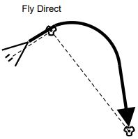
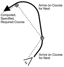
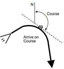
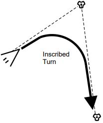
Navigation Options parameters define the heading The direction that the aircraft is pointing. or course of the aircraft at the beginning of the procedure and the direction of turns taken to arrive at the procedure site.
Table - Navigation Options Parameters![]()
Enroute Options
| Field | Description |
|---|---|
| Reduce Turn Radii | Select this check box to force the aircraft to use the minimum speed for computing the normal turn radius. The maximum speed radius will only be generated if the turn sequence at that radius is the same as the minimum radius. If the aircraft is flying at a very high speed, it may exceed its Turn G limit in this mode. |
| Turn Factor | The Turn Factor is the maximum amount - expressed as a multiplier - that the turn radius will be increased to minimize the bank angle required to complete the turn. The full circles that correspond (or are tangent) to the start/stop turns at the extended radius may not intersect if the Turn Factor is set high enough. This parameter is a limit and may not actually be achieved due to the requirement to generate an appropriate turn sequence. You can adjust the slider or enter the value manually in the box, with the minimum value being 1 and the maximum value being 10. |