Part 16:
STK Premium (Space), or STK Enterprise
You can obtain the necessary licenses for this training by contacting AGI Support at support@agi.com or 1-800-924-7244.
The results of the tutorial may vary depending on the user settings and data enabled (online operations, terrain server, dynamic Earth data, etc.). It is acceptable to have different results.
Capabilities Covered
This lesson covers the following STK Capabilities:
- STK Pro
- Astrogator
Problem
Engineers and operators require a quick way to design high-fidelity spacecraft trajectories for mission planning and operations. In this scenario, they will design a launch from a launch pad, and successfully inject a satellite into a geosynchronous equatorial orbit (GEO).
Solution
Use STK's Astrogator capability to design:
- A basic launch phase to place a satellite into a parking orbit (low Earth orbit or LEO)
- A transfer orbit injection (TOI) maneuver to transfer from LEO to GEO
- A synchronized orbit injection (SOI) maneuver to circularize the orbit at GEO
What You Will Learn
Upon completion of this tutorial, you will have a basic understanding of:
- Astrogator
-
The Launch Vehicle Object
Video Guidance
Watch the following video. Then follow the steps below, which incorporate the systems and missions you work on (sample inputs provided).
Create a New Scenario
Create a new scenario.
- Launch STK (
 ).
). - In the Welcome to STK window, click Create a Scenario.
- Enter the following in the New Scenario Wizard:
- When finished, click .
- When the scenario loads, click Save (
 ). A folder with the same name as your scenario is created for you in the location specified above.
 - Verify the scenario name and location.
- Click .
| Option | Value |
|---|---|
| Name: | STK_Astrogator |
| Location: | Default |
| Start: | Default |
| Stop: | + 5 days |
Save Often!
Update the Insert STK Objects tool
Ensure the Launch Vehicle (![]() ) appears in the Insert STK Objects tool.
) appears in the Insert STK Objects tool.
- Click on the Insert STK Objects tool.
- In the New Object list, select the object you want to add.
- Click .
Launch Vehicle
Insert a Launch Vehicle Object.
- Select Launch Vehicle (
 ) in the Insert STK Objects tool.
 - Select the Insert Default method.
- Click .
- Rename LaunchVehicle1 () LaunchToLEO.
Simple Ascent Propagator
Use the simple ascent propagator to define the ascent trajectory from a launch point to an orbit insertion point.
- Open LaunchToLEO's () properties (
 ).
). - Select the Basic - Trajectory page.
- Ensure Propagator is set to SimpleAscent.
- Set the Burnout Velocity value to 7.3 km/sec. This will keep the resulting orbit near circular.
- Click to accept the changes and keep the Properties Browser open.
- Select the 2D Graphics - Attributes page.
- Change the Color: to teal.
- Click to accept the changes and close the Properties Browser.
View the Launch Vehicle Trajectory
View LaunchToLEO's (![]() ) launch vehicle trajectory and ground track in the 3D Graphics Window.
) launch vehicle trajectory and ground track in the 3D Graphics Window.
- Bring the 3D Graphics window to the front.
- Zoom To LaunchToLEO ().
- Use your mouse to zoom out so you can see the launch vehicle trajectory and ground track.
- Note that the Launch Vehicle's () default location is Cape Canaveral.
- Notice the trajectory ends at burnout.
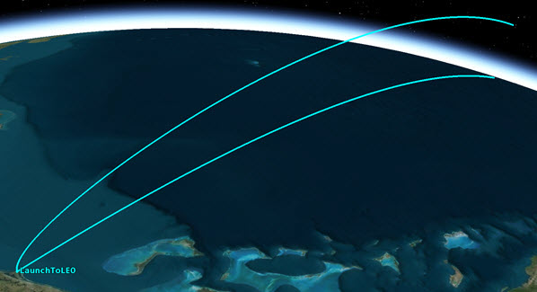
Launch Vehicle Trajectory
Insert A Satellite
Insert a Satellite (![]() ) object which you will use to create the satellite orbit.
) object which you will use to create the satellite orbit.
- Select Satellite (
 ) in the Insert STK Objects tool.
 - Select the Insert Default method.
- Click .
- Rename Satellite () GEO_Sat.
Astrogator
Set GEO_Sat's Propagator to Astrogator. You will use Astrogator to design your spacecraft trajectory.
- Open GEO_Sat's () properties ().
- Select the Basic - Orbit page.
- Set Propagator: to Astrogator.
Mission Control Sequence
The Mission Control Sequence (MCS) is the core of your space mission scenario. The MCS functions as a graphical programming language, in which mission segments dictate how Astrogator calculates the trajectory of the spacecraft based on the general settings that you specify for the MCS itself.
The MCS is defined by selecting and organizing MCS Segments in a manner that produces your desired trajectory. By default, an Astrogator satellite's MCS contains two segments: an Initial State (![]() ) segment and a Propagate (
) segment and a Propagate (![]() ) segment.
) segment.
Initial State Segment
Since you model a Launch Vehicle (![]() ), remove the Initial State (
), remove the Initial State (![]() ) segment. You will replace it with a Follow (
) segment. You will replace it with a Follow (![]() ) segment .
) segment .
- Select Initial State (
 ) in the MCS.
 - Click Delete Segment (
 ).
). - Click to confirm deletion.
Follow Segment
Use the Follow (![]() ) segment to set GEO_Sat (
) segment to set GEO_Sat (![]() ) to follow LaunchToLEO (
) to follow LaunchToLEO (![]() ), and then separate from LaunchToLEO (
), and then separate from LaunchToLEO (![]() ) at the end of its ephemeris.
) at the end of its ephemeris.
- Right-click the Propagate (
 ) segment in the MCS.
 - Select Insert Before...
- Select Follow (
 ) in the Segment Selection window.
 - Click .
- Ensure Follow () is selected in the MCS.
- Select the General tab on the Basic - Orbit page.
- Click the Leader: ellipsis button (
 ).
). - Select LaunchToLEO () in the Select Leader window.
- Click .
- Set Joining: to Join at End of Leader's Ephemeris in the Additional Options section.
By selecting this joining parameter, GEO_Sat (![]() ) uses the LaunchToLEO's (
) uses the LaunchToLEO's (![]() ) final ephemeris point as the initial and final state of the Follow Segment. Also, the separation parameter is automatically set to "Separate at End of Leader's Ephemeris".
) final ephemeris point as the initial and final state of the Follow Segment. Also, the separation parameter is automatically set to "Separate at End of Leader's Ephemeris".
Fuel Tank Configuration
Set GEO_Sat's (![]() ) fuel mass and its maximum fuel mass.
) fuel mass and its maximum fuel mass.
- Select the Fuel Tank tab.
- Set the following in the order shown:
- Click .
| Option | Value |
|---|---|
| Maximum Fuel Mass: | 6000 kg |
| Fuel Mass: | 5000 kg |
Run the Mission Control Sequence
Run the Mission Control Sequence to calculate the trajectory of the spacecraft.
- Select Propagate () in the MCS.
- Note the current stopping condition is Duration with a Trip: value of 43200 sec (0.5 day).
- Click Run Entire Mission Control Sequence (
 ) in the MCS toolbar.
 - When finished, bring the 3D Graphics window to the front.
- Click Home View (
 ) to view GEO_Sat's () trajectory.
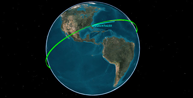
Satellite in a Low Earth Orbit
Satellite Engine Model
Use a realistic engine model in order to produce accurate results.
- Click Component Browser (
 ) in the MCS Toolbar.
 - Change Show: to Astrogator Components on the Component Browser window.
- Select Engine Models in the Components list on the left.
- Select Constant Thrust and Isp in the Engine Models list on the right.
- Click duplicate (
 ).
). - Change Name: to Test Engine in the Field Editor window.
- Click .
- Double-click on Test Engine in the Engine Models list.
Modify Constant Thrust and Isp
Modify the Constant Thrust and Isp engine model to specify the thrust and Isp for your engine.
- Double-click on Thrust in the Engine Models - Test Engine window.
- Set Real Number: to 13500 N in the Real Number Field window.
- Click .
- Double-click on Isp in the Engine Models - Test Engine window.
- Set Real Number: to 2000 s in the Real Number Field window.
- Click .
- Click to close the Engine Models - Test Engine window.
- Close (
 ) the Component Browser.
This high value will only affect the amount of fuel that we burn through over the course of the maneuvers. We are doing this so that we do not need to modify the spacecraft mass values several times over the course of the mission.
Transfer Orbit Injection (TOI)
Use the Propagate segment (![]() ) to fly to the first maneuver time. The orbit is circular and therefore the burn can take place at any time and result in a similar delta-v. You require an inclination as close as possible to zero once you enter GEO. In order to minimize the required delta-v to both circularize and change inclination at GEO, we will combine those maneuvers into one. For that to be successful, the apogee of the transfer orbit will be the ascending or descending node of the orbit. This can be achieved by starting the TOI burn on either the ascending or descending node.
) to fly to the first maneuver time. The orbit is circular and therefore the burn can take place at any time and result in a similar delta-v. You require an inclination as close as possible to zero once you enter GEO. In order to minimize the required delta-v to both circularize and change inclination at GEO, we will combine those maneuvers into one. For that to be successful, the apogee of the transfer orbit will be the ascending or descending node of the orbit. This can be achieved by starting the TOI burn on either the ascending or descending node.
- Return to GEO_Sat's () properties ().
- Right-click on Propagate () in the MCS.
- Select Rename.
- Change the name to Prop_to_TOI.
Update the Stopping Condition
Update the Propagate Stopping Condition to stop at the ascending node after 2 full revolutions in the parking orbit.
- Click New (
 ) in the Stopping Conditions section.
 - Select AscendingNode in the New Stopping Condition window.
- Click .
- Select the Duration stopping condition.
- Click Delete ().
- Change Repeat Count: to 2 so will stop it on the second ascending node.
- Click .
- Click Run Entire Mission Control Sequence ().
Define a Target Sequence - Start Transfer
Insert a Target Sequence (![]() ). We will use a Target Sequence to calculate the Delta-V required to move GEO_Sat (
). We will use a Target Sequence to calculate the Delta-V required to move GEO_Sat (![]() ) into a transfer orbit.
) into a transfer orbit.
- Return to GEO_Sat's () properties ().
- Right-click on Prop_To_TOI () in the MCS.
- Select Insert After...
- Select Target Sequence (
 ) in the Segment Selection window.
 - Click .
- Right-click on Target Sequence () in the MCS.
- Select Rename.
- Change the name to Start_Transfer.
Insert a Maneuver Segment
Insert a Maneuver (![]() ) Segment. This first maneuver delta-v will be solved to achieve a particular altitude at the end of the transfer ellipse.
) Segment. This first maneuver delta-v will be solved to achieve a particular altitude at the end of the transfer ellipse.
- Right-click on Start_Transfer () in the MCS.
- Select Insert After...
- Select Maneuver (
 ) in the Segment Selection window.
 - Click .
- Drag and drop the Maneuver () Segment below Start_Transfer ().
- Right-click on the Maneuver () Segment.
- Select Properties...
- Change Name: to TOI
- Change Color: to white.
- Click .
The Maneuver (![]() ) Segment appears below the Return (
) Segment appears below the Return (![]() ) Segment.
) Segment.
Insert a Propagate Segment
Insert a Propagate (![]() ) segment that will be used to determine the stopping condition.
) segment that will be used to determine the stopping condition.
- Right-click on TOI () in the MCS.
- Select Insert After...
- Select Propagate () in the Segment Select window.
- Click .
- Right-click on the new Propagate () Segment.
- Select Properties...
- Set Name: to Transfer.
- Set Color: to Yellow.
- Click .
- Click .
Set the Engine Model
Use the Test Engine model you updated earlier.
- Select TOI () in the MCS.
- Select the Engine tab.
- Click the Engine Model ellipsis button () in the Propulsion Type section.
- Select Test Engine (
 ) in the Select EngineModel window.
 - Click .
Select the Control Parameter
Select Delta-V Magnitude as the independent variable.
- Select the Attitude tab.
- Note that the default Attitude Control: is Along Velocity Vector (body X).
- Click the target icon (
 ) to target the Delta-V Magnitude and make it the independent variable.
 - Click .
This tells Astrogator to determine the delta-v magnitude based on user determined results. We will set up those results in an upcoming section.
Propagate to Apoapsis
Update the Transfer (![]() ) Stopping Condition to stop at Apoapsis.
) Stopping Condition to stop at Apoapsis.
- Select Transfer () in the MCS.
- Click New () in the Stopping Conditions section.
- Select Apoapsis (
 ) in the New Stopping Condition window.
 - Click .
- Select Duration in the Stopping Conditions section.
- Click Delete ().
- Click .
Select the Results Variable
Set the radius of orbit, R Mag, as the equality constraint. Astrogator will use R Mag to determine the required delta-v magnitude.
- Select Transfer () in the MCS.
- Click at the bottom of the MCS.
- Expand (
 ) Spherical Elems in the User - Selected Results window's Available Components: list.
 - Move (
 ) R Mag () to the selected components list. This will allow you to set the radius of orbit at the end of the Propagate Segment.
 - Click .
Set Up the Targeter
Set up the differential corrector profile to change the Delta-V Magnitude to achieve a desired radius of orbit.
- Select Start_Transfer () in the MCS.
- Change Action: to Run active profiles.
- Select Differential Corrector in the Profiles section.
- Click Properties ().
Set the Control Parameter
Use Delta-V Magnitude as the Control Parameter (independent variable).
- Locate the Control Parameters section of the Differential Corrector window.
- Select Use for ImpulsiveMnvr.Pointing.Spherical.Magnitude.
Set the Equality Constraints (Results)
Use R_Mag as the Equality Constraint (dependent variable), and set the radius of orbit goal to be 42238 km.
- Locate the Equality Constraints (Results) section of the Differential Corrector window.
- Select Use for R_Mag.
- Select the Desired Value field.
- Set Desired Value to 42238 km.
- Click .
- Click .
Run Entire Mission Control Sequence
- Save () your scenario
- Click Run Entire Mission Control Sequence ().
- When complete, look at the top of STK. You will see a message informing you whether or not running the entire mission control Sequence converged or didn't converge.
- Look at the StartTransfer.Differential Corrector data window which shows you data based on running the active profile.
- Bring the 3D Graphics window to the front. You can see the iterations, the last one placing the satellite at the desired location and altitude.
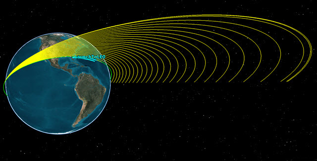
TOI Iterations
Define a Target Sequence - Finish Transfer
Now that the transfer has been analyzed, a similar process will be followed to create the SOI maneuver and circularize the orbit at GEO, and at the same time, bring the inclination to 2 deg. We will target the inclination slightly above the desired inclination, so that it will drift down to the desired inclination (0 to 1 degree) over time.
- Return to GEO_Sat's () properties ().
- Right-click on the bottom Return (
 ) Segment in the MCS.
 - Select Insert Before...
- Select Target Sequence () in the Segment Selection window.
- Click .
- Right-click on Target Sequence () in the MCS.
- Select Rename.
- Change the name to Finish_Transfer.
Insert a Maneuver Segment
Insert a Maneuver (![]() ) Segment. We will solve for the X (Velocity) & Y (Normal) components, the Delta-V vector in those references axes, needed to achieve a circular orbit at GEO.
) Segment. We will solve for the X (Velocity) & Y (Normal) components, the Delta-V vector in those references axes, needed to achieve a circular orbit at GEO.
- Right-click on Finish_Transfer () in the MCS.
- Select Insert After...
- Select Maneuver () in the Segment Selection window.
- Click .
- Drag and drop the Maneuver () Segment below the Finish_Transfer ().
- Right-click on the Maneuver () Segment.
- Select Properties...
- Change Name: to SOI.
- Change Color: to white.
- Click .
The Maneuver (![]() ) Segment appears below the return (
) Segment appears below the return (![]() ) Segment.
) Segment.
Insert a Propagate Segment
Insert a Propagate (![]() ) Segment will be used to determine the stopping condition.
) Segment will be used to determine the stopping condition.
- Right-click on SOI () in the MCS.
- Select Insert After...
- Select Propagate () in the Segment Select window.
- Click .
- Right-click on the new Propagate () Segment.
- Select Properties...
- Set Name: to Prop1Rev.
- Set Color: to Blue.
- Click .
- Click .
Set the Engine Model
Use the Test Engine model you updated earlier.
- Select SOI () in the MCS
- Select the Engine tab.
- Click the Engine Model ellipsis button () in the Propulsion Type section.
- Select Test Engine () in the Select EngineModel window.
- Click .
Select the Control Parameter
Use Thrust Vector as the attitude control setting. Then select the Delta-V vector's Cartesian X (Velocity) and Y (Normal) as the independent variables.
- Select the Attitude tab.
- Set Attitude Control: to Thrust Vector.
- Click the target icon () next to X (Velocity).
- Click the target icon () next to Y (Normal).
- Click .
Propagate for One Day
Update the Prop1Rev (![]() ) Duration Stopping Condition to stop after 1 day.
) Duration Stopping Condition to stop after 1 day.
- Select Prop1Rev () in the MCS.
- Change Trip: to 86400 sec (1 day) in the Stopping Conditions section.
- Click .
Select the Results Variable
Set Eccentricity and Inclination as the equality constraints.
- Select Prop1Rev () in the MCS.
- Click at the bottom of the MCS.
- Expand () Keplerian Elems in the User - Selected Results window's Available Components: list.
- Move () Eccentricity () to the selected components list.
- Move () Inclination () to the selected components list.
- Click .
Set Up the Targeter
Set up the differential corrector profile to change the Delta-V Magnitude to achieve a desired radius of orbit.
- Select Finish_Transfer () in the MCS.
- Change Action: to Run active profiles.
- Select Differential Corrector in the Profiles section.
- Click Properties ().
Set the Control Parameter
Use Delta-V vector's Cartesian X (Velocity) and Y (Normal) as the Control Parameters (independent variables).
- Locate the Control Parameters section of the Differential Corrector window.
- Select Use for ImpulsiveMnvr.Pointing.Cartesian.X.
- Select Use for ImpulsiveMnvr.Pointing.Cartesian.Y.
Set the Equality Constraints (Results)
Set Eccentricity and Inclination as the Equality Constraints (dependent variables). Target an Eccentricity of 0 within a 0.001 tolerance, and a 2 deg Inclination within 0.01 deg tolerance.
- Locate the Equality Constraints (Results) section of the Differential Corrector window.
- Select Use for Eccentricity.
- Set Tolerance to 0.001.
- Select Use for Inclination.
- Select the Desired Value field.
- Set Desired Value to 2 deg.
- Set Tolerance to 0.01 deg.
- Set Method: to By tolerance in the Scaling section.
- Click .
- Click .
Run Entire Mission Control Sequence
- Save () your scenario
- Click Run Entire Mission Control Sequence ().
- Look at the Finish Transfer.Differential Corrector data window which shows you data based on running the active profile.
- Bring the 3D Graphics window to the front. You can see the iterations, the last one placing the satellite at the desired eccentricity and inclination.
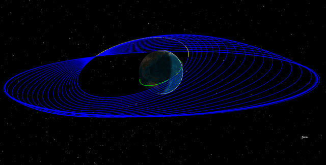
SOI Iterations
Remove Iterations
Remove the visible iterations in the 3D Graphics window.
- Return to GEO_Sat's () properties ().
- Right-click on the Bottom Return (
 ) Segment.
 - Select Insert Before...
- Select Propagate () on the Segment Selection window.
- Click .
- Click Run Entire Mission Control Sequence ().
- Bring the 3D Graphics window to the front.
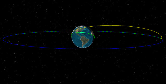
Final Orbit
MCS Segment Summary Report
The MCS Segment Summary report provides run summary data for the currently selected segment in the MCS tree. The summary report gives information on maneuver times, expected delta-v magnitude, estimated burn duration, estimated fuel usage and other important data.
- Return to GEO_Sat's () properties ().
- Select Start_Transfer () in the MCS.
- Click Summary (
 ) in the MCS Toolbar.
 - When finished, close () the summary report.
- Select Finish_Transfer ().
- Click Summary () in the MCS Toolbar.
- When finished looking through the report, close any reports, tools and properties you still have open.
- Save () your work.
Summary
This was a basic introduction to Astrogator. In this lesson, you:
- Used a Launch Vehicle object to launch a vehicle that followed an ascent trajectory from a launch point to an orbit insertion point.
- Inserted a Satellite object, switched the propagator to Astrogator, and used a Follow Segment. This allowed the Satellite to follow the Launch Vehicle object, to separate from the Launch Vehicle at the end of its trajectory, and to place the Satellite object into a LEO.
- Used a Target Sequence, a Maneuver Segment, and a Propagate Segment, to place the Satellite orbit into a TOI.
- Finalized its orbit by creating another Target Sequence which placed the Satellite into a GEO.
- Used an MCS Segment Summary Report to determine maneuver times, required delta-v, estimated burn duration, and estimated fuel usage.
On Your Own
Throughout the tutorial, hyperlinks were provided that pointed to in depth information of various tools and functions. Now is a good time to go back through this tutorial and view that information. Further Astrogator tutorials can be found HERE.