STK Premium (Air) or STK Enterprise
You can obtain the necessary licenses for this tutorial by contacting AGI Support at support@agi.com or 1-800-924-7244.
Capabilities Covered
This lesson covers the following STK Capabilities:
- Aviator Pro
Editing Missile Properties
STK's Aviator Pro capability enables you to model the performance characteristics of missiles in addition to aircraft. You can create a missile model in the User Missile Models catalog of the Aviator catalog interface or catalog manager.
The Missile properties window is used to define the global settings and performance models of a missile model in your User Missile Models catalog. Any changes that you make in this window are applied to the missile's definition in the catalog.
The Missile properties window is comprised of three tabs - Performance Models, Aerodynamics, and Propulsion. The Performance Models tab defines the basic turning, climb and descent transition, cruising, and attitude transition characteristics of the missile, while the Aerodynamics and Propulsion tabs allow you to select and define strategies to model attitude and propulsion characteristics, respectively.
When you are done editing the missile's properties, click Save to save any changes you have made and click Close to close the window; you will be prompted to save any changes before closing the window.
Performance Models
The Performance Models tab is comprised of five sections - Level Turns, Attitude Transitions, Climb, Cruise, and Descent - as described below. As they do with aircraft models, performance models define the behavior of the missile in flight.
Level Turns
The Max Load Factor that the missile can withstand while maneuvering. The value specified for this parameter is the level turn value for the missile. Aviator adheres to this value when possible, but in procedures where the turn is non-level the value may be adjusted to maintain the correct relationship between this and other interrelated parameters.
Accel Maneuver Mode Field
You can toggle if the aircraft turn or push/pull calculations use atmosphere density scaling. Alternatively, you can define specific parameters used in the turn calculation for more realistic results. Activating aero/prop maneuver mode will cause trajectory to be constrained by the defined parameters.
Table -Accel Maneuver Mode Options![]()
Attitude Transitions
Missile attitude is determined using a 123 Euler angle sequence of Bank, Angle of Attack The angle between the body X axis and the projection of the velocity vector onto the body XZ plane. The velocity vector is the velocity of the object as observed in the object's central body fixed coordinate system., and Sideslip, originating from a velocity aligned, nadir constrained set of axes. Attitude rates may be violated in the case of very short - or zero distance - procedures.
Table - Attitude Transitions Parameters![]()
Always Ignore Flight Path Angle for Climb and Descent Transactions
When you are working at the design limits of an aircraft model, you may commonly encounter problems with:
- pushing over at high path angles
- pulling up at low flight path angles
For example, an aircraft flying at high altitude and high speed may not have enough control authority to push over as a procedure requires. Or, the aircraft may need to violate another constraint such as the procedure ceiling.
In these situations, you can select the Always Ignore Flight Path Angle check box to ignore load factor limits. This option enables you to suspend these limits without needing to change to the aircraft model that you are using.
Climb
The Climb performance model is comprised of a simple set of parameters that define the flight characteristics of the missile while climbing.
Table - Attitude Transitions Parameters![]()
Cruise
The Cruise performance model is comprised of a simple set of parameters that define the flight characteristics of the missile while cruising.
Table - Attitude Transitions Parameters![]()
Descent
The Descent performance model is comprised of a simple set of parameters that define the flight characteristics of the missile while descending.
Table - Attitude Transitions Parameters![]()
Limit Fields
Optionally, you can define limits to the performance model system to augment the values used for climb, cruise, and descent performance model speeds. Select the check box next to the applicable limit(s) to use.
Aviator does not check if these limits are compatible with the specified Climb, Cruise, and Descent speeds. If they are mismatched, the system can allow the speed during a climb or descent to momentarily violate one of the limits, even though the ending speed satisfies the limits.
Dynamics/Moments
The Dynamics/Moments tab allows you to specify control parameters for the aircraft. These allow calculation of aircraft performance characteristics, but are not used to calculate trajectory. Required Control Authority allows you to specify what angular rates are expected to safely control the vehicle. Control Surface Buildup allows Aviator to calculate control forces available in each axis and is used to compute flight profile Control Force Required and FullControl.
Aviator calculates control forces as torques throughout the flight. The max force available for the torque is determined from Surface Area, CLMax, and flight conditions based on:
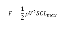
| Item | Description |
|---|---|
| F | Force |
| p | Air density determined by aircraft altitude |
| V | Aircraft velocity |
| S | Surface area determined above |
The max available control torque along an axis is the product of this force and the proscribed Moment Arm Length.