Polarization
Polarization is a property of an electromagnetic wave that describes the orientation of the electric field vector with reference to the antenna's orientation. The following figure illustrates the three basic types of polarization:
Some antenna polarization types
In the illustration of linear polarization, the electrical field is polarized in the y direction in the coordinate system. In special cases of linear polarization, the electrical field aligns vertically or horizontally with reference to the antenna. In the other two types of orientation shown, the tip of the E vector describes an ellipse and a circle, respectively, as it rotates over time. Circular polarization can be right-handed (as in the illustration) or left-handed.
STK computes the polarization match, which is a quantity between a transmitter and a receiver based on their polarization types, positions, and attitudes.
See Kraus, John D., Antennas, 2nd ed., New York: McGraw-Hill (1988), pp. 70-73.
For a simple receiver or transmitter model, you select the polarization type on the Model Specs tab. For all other receivers and transmitter models, you select the polarization type on the Antenna's Model Specs tab.
See the Technical Notes for a discussion of signal loss due to polarization mismatch.
Polarization Types
STK Communications makes the following polarization types available:
- Elliptical: The receiver is elliptically polarized. The vector describing the orientation of the electrical field with reference to the antenna describes an ellipse as it rotates over time.
- Horizontal: The receiver is linearly polarized, and the electrical field is aligned with the reference axis.
- Left-hand Circular: The receiver is configured to receive left-hand circularly polarized transmissions.
- Linear: The receiver is linearly polarized with the electrical field aligned with the reference axis.
- Right-hand Circular: The receiver is configured to receive right-hand circularly polarized transmissions.
- Vertical: The receiver is linearly polarized, and the electrical field is orthogonal to the reference axis.
Polarization Parameters
Depending on the polarization type chosen, the following parameters are available for specification:
Polarization parameters
The following figure illustrates tilt angle and axial ratio for the elliptical polarization type:
Polarization parameters for elliptical polarization type
The polarization match between the transmitting and receiving object is calculated dynamically on a scale of 0 to 1, where 0 is no match and results in no received signal, and 1 is perfect (no loss).
Currently, depolarization due to rain is not supported.
For certain complex antennas, you cannot specify Polarization Type and Polarization Parameters because polarization is instead computed using the complex gain pattern.
Radar Signal Polarization
You can set a polarization type for a Radar’s transmit side signal and one for its receiver side signal. Transmit signal polarization interacts with the target Radar Cross Section (RCS) and is modified based on the polarized RCS type. The updated polarized signal is received by the Radar receiver and interacts with the receive side polarization. For more information on Polarized RCS types, refer to Radar Target RCS Complex Polarization Scattering Matrix. You also can enable a parallel radar channel with an orthogonal polarized signal and identical system characteristics. For more information, see Orthogonal Polarization.
For information on computing polarization data, see Analyzing Polarization on Radar Performance.
Transmit Side Polarization
Radar transmit side polarization is used to polarize the transmitted signal on the radar antenna’s body-axis. The default antenna orientation aligns the antenna boresight (direction of signal propagation) to the Z-axis of the body. The electric E-field may be aligned to reference X-axis or Y-axis. The terms vertical and horizontal refer to the E-field being perpendicular or along the reference axis. For example, X-axis is being used as the reference axis; the horizontal polarization will align the E-field vector along the X-axis, while vertical polarization will place the E-field vector perpendicular to the X-axis. The tilt angle with linear polarization will place the E-field at the tilt angle from the reference axis.
The computation of the final orientation of the polarization vector uses the attitude of the object, parent/grandparent objects and also depends on the direction vector to the target.
Receive Side Polarization
The receive side polarization for radar sets the receive antenna polarization on the receive antenna body axis. The Z-axis is the default antenna orientation along the boresight.
The polarization reference axis settings on the receive side are like the settings on the transmit side.
Whenever transmit polarization is set, the receiver side must also be set to compute the polarization mismatch loss.
Transmit and Receive Orthogonal Polarization
Radar target reflections respond differently to diverse signal polarizations. Radars use orthogonal signal polarizations to elicit a different response from the target. Select Enable Transmit/Receive Orthogonal polarization to create a secondary signal channel with exactly the same system characteristics, but with a polarization setting orthogonal to the original channel. In other words, you model the orthogonal channel with the same frequency, power, and signal attributes, etc.
You can use the orthogonal channel independently on the transmit side or the receiver side of the radar system. The orthogonal polarizations are created by STK based on the polarization of the original channel. Examples of the orthogonal polarization pairs include:
- Vertical & horizontal
- RHC & LHC
- Linear with tilt angle & Linear with tilt angle plus 90 degrees
In case of the elliptical polarization settings, the orthogonal channel contains the settings which are diagonally opposite on the Poincare polarization sphere.
The targets with a complex valued scattering RCS may respond differently to the two incoming signals and may create up to four reflections. The following diagram implies a bistatic operational mode, but the radar configuration may be monostatic. The same analytical capability applies regardless of the radar receiver's position and whether it shares an antenna for transmitting or receiving.
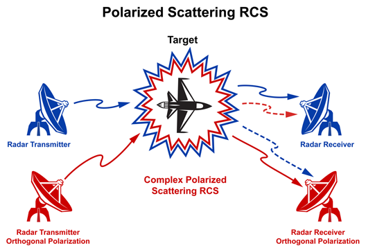
The four reflections may be received by the two orthogonally polarized receiver channels. These signals are combined in the signal post processing system to compute the individual channel and aggregate system performance data.
Radar Target RCS Complex Polarization Scattering Matrix
STK supports fixed as well as aspect dependent symmetric, mono-static, and bi-static Radar Cross Sections (RCS) for all types of radar target objects. For more information, see Radar Cross Section (RCS).
The aspect dependent user RCS data is provided in a simple text file. See External RCS Files for an example and format of an RCS file.
Radar Jammer Polarization
Other mono-static radars and RF transmitters may act as jammers to a radar receiver. Starting with STK 9, polarization has been extended to the jamming signals. Each (orthogonal) polarized receiver is matched to the incoming jamming signal polarizations to compute the impact of the interference on its performance, as shown below.
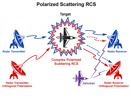
Jammer polarized signals also undergo the same attitude and orientation computations as other radar signals to process the polarization mismatch to the radar receiver.
When the jammers are not polarized, then STK skips the polarization mismatch computation to the radar receiver's main and orthogonal channels. In this case, the jammer will the same impact on each channel.
Analyzing Polarization on Radar Performance
You can generate reports that provide the following data:
- The polarization impact on performance of the radar’s main channel.
- When the main channel radar receiver is experiencing jamming.
- The radar’s orthogonal polarization channel.
- The orthogonal channel under threat of jamming.
For more information on Radar Polarization data providers, see Radar Polarization Data Providers.