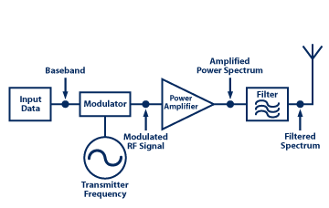
STK Communications offers a variety of spectrum filters. These filters may be enabled on (or attached to) the transmitter, receive, and/or radar objects. The filters, when attached to a transmitter, change the power spectrum density (PSD) of the RF spectrum at the output of the final power amplifier of the transmitter. The filter's insertion loss may also change the output power of the amplifier as well. The arrangement is shown in the following block diagram:
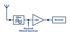
In receive mode, the received spectrum may be filtered again before being amplified by the receiver's low noise amplifier. The receiver front end block diagram shows the signal flow:
The filter's frequency response characteristics are defined with the signal carrier frequency as the (midband) reference. The carrier represents the 0 Hz on the filter's frequency curve. The filter's bandwidth is defined as + limit on either side of the signal carrier frequency.
STK Communications Supported Filters
These technical notes provide a brief description of the frequency transfer characteristics for the filters provided, as built in functions, in STK Communications. You also have the option to use filters with arbitrary frequency transfer characteristics by listing the frequency response data in an external file.
Bessel Filter
The filter's frequency response curve is modeled by the following equation:
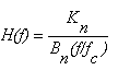
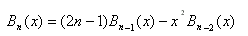
The Bessel recursion relation is used to compute the Bessel coefficients ![]() :
:
where
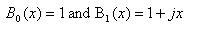
is the filter's cutoff frequency
Couch II, Leo W., Digital and Analog Communications, New York: Prentice Hall (1977), section 4.8.
Butterworth Filter
A general form of nth order Butterworth filters is modeled as:
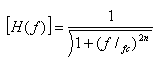
where
is the filter's cutoff frequency and n is the order of the filter.
Couch II, Leo W., Digital and Analog Communications, New York: Prentice Hall (1977), section 4.8.
Chebyshev Filter
The model equation is:
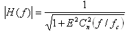
where E is a design constant and ![]() is the nth Order Chebyshev polynomial computed by the recursion relation:
is the nth Order Chebyshev polynomial computed by the recursion relation:
![]()
Couch II, Leo W., Digital and Analog Communications, New York: Prentice Hall (1977), section 4.8.
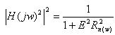
RC Low Pass Filter
Simple RC Low Pass filter characteristics are modeled by the equation:
![]()
where ![]() is the filter's 3dB cutoff frequency.
is the filter's 3dB cutoff frequency.
Couch II, Leo W., Digital and Analog Communications, New York: Prentice Hall (1977), section 2.6.
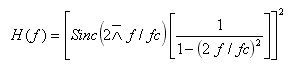
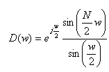
Sinc Filter
This filter will model normalized the  characteristic response, where:
![]()
The cutoff frequency is the frequency of the first null point of the response curve. The subsequent nulls will occur at the integer multiples of the cutoff frequency.
Elliptic Filter
Elliptic filters are modeled by the characteristic magnitude response function:
The details of the algorithm can be found in the following reference.
Poularikas, Alexander D. (Editor), The Handbook of Formulas and Tables for Signal Processing, CRC & IEEE Press (1998).
Rectangular Filter
Rectangular filters are unit magnitude flat spectrum filters with very sharp cutoffs at the upper and the lower filter band limits.
FIR Filter
The Finite Impulse Response filters are defined by the characteristics models:
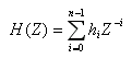
in the Z- domain.
The frequency response is by definition:
![]()
The filter order is the total number of taps (coefficients) where![]() coefficients are the filter tap coefficients and may be complex. N is the total number of taps in the FIR filter.
coefficients are the filter tap coefficients and may be complex. N is the total number of taps in the FIR filter.
Frerkring, Marvin E. (Editor), Digital Signal Processing in Communication Systems, New York: Van Nostrand Reinhold (1996).
FIR_BoxCar Filter
This filter is a simpler version of the FIR filter. All the filters tab coefficients are set to unity. The filter's order represents the total number of the taps on the filters.
Frerkring, Marvin E. (Editor), Digital Signal Processing in Communication Systems, New York: Van Nostrand Reinhold (1996).
IIR Filter
The infinite response filters are modeled by the characteristic response:
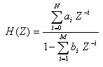
where ![]() and
and  may be complex coefficients.
Frerkring, Marvin E. (Editor), Digital Signal Processing in Communication Systems, New York: Van Nostrand Reinhold (1996).
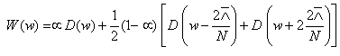
Cosine Window Filter
This filter models the window function applied to the data to limit the spectrum. The model equations are:
![]() = data sample rate.
= data sample rate.
Hamming, R. W., Digital Filters, section 8.9.
Gaussian Filter
This filter models a classical Gaussian curve as a filter characteristic response, which may be used as a filter to modify the spectrum.
The sampling frequency and the filter order determines the spread of the Gaussian Curve. The ratio of the sampling frequency to the filter order equals the 1-sigma point of the Gaussian Curve. Increasing the order will decrease the frequency where 1-sigma point occurs and the curve will drop faster.
Hamming Window Filter
The spectrum of the Hamming window may be modeled by:
where

Poularikas, Alexander D. (Editor), The Handbook of Formulas and Tables for Signal Processing, CRC & IEEE Press (1998).