Phased Array Antenna
The Phased Array Antenna model consists of many radiating elements. Each element is modeled as an isotropic pattern. By modifying the excitation (amplitude and phase) of each element differently, a phased array antenna can electronically steer its maximum gain toward a particular direction or main radiation axis. A phased array antenna not only can steer its maximum gain in a particular direction, but it can also steer nulls toward other directions to prevent radiation to and from other directions. The act of altering each element’s excitation is effectively accomplished through the assignment of weights to each element. This set of weights for a particular direction is called a steering vector and each weight is a complex number.
The Phased Array Antenna configuration is broken down into following areas:
- General parameters - a set of parameters general to the antenna
- Element Configurations
- Beam Direction Providers
- Null Direction Providers
- Beamformers
Element Configurations, Beam and Null Directions Providers, and Beamformers are subsections with specialized parameters.
The Phased Array Antenna model uses angles that are measured in a spherical coordinate system. See Phased Array Antenna coordinate system for additional information.
General parameters
The following general antenna parameters appear at the top of the Antenna tab of the Basic - Definition page in the Phased Array Antenna's Properties Browser.
| Parameter | Description |
|---|---|
| Design Frequency |
This is the frequency of the antenna. The antenna design frequency is independent of the operational frequency of a transmitter, receiver, or radar. Changing the frequency of a transmitter, receiver, or radar does not update an embedded antenna's design frequency, nor vice versa. The design frequency is solely used at antenna configuration time to compute the antenna size from its max gain or beamwidth settings. A mismatch between signal frequency and antenna design frequency typically causes performance degradation. |
| Backlobe Suppression | Enter the amount of attenuation to apply to any angle in the back hemisphere. This enables you to model reduced gains due to a back plane or other type of physical construct that would hinder reception from the back side of the antenna. |
| Backlobe Suppression Type |
Constant. Applies the same Backlobe Suppression value to all angles. Cosine. Applies the Backlobe Suppression value as a function of the cosine of the angle with complete suppression when the angle is 0 degrees and the Backlobe Suppression value is at a 90-degree angle. |
| Element Factor |
Include Element Factor. Selecting this check box includes the individual element pattern. When selected, this will use a general raised cosine function. Clearing the check box can be helpful when comparing with other tools that only consider the array factor. When cleared, be aware that the maximum gain will not vary with the steering angle. Raised Cosine Exponent. Produces the cosine raised to the exponent power you specify. |
| Dimension |
Elements. Enter the number of enabled elements. Width. Enter the length, in meters, of the antenna. Height. Enter the height, in meters, of the antenna. |
Element Configurations
The Element Configuration tab enables you to define the physical aspects of the antenna elements. It consists of two parts: a Viewport and a Designer section. The Viewport section shows the layout of the currently configured elements. The Designer section enables you to change the physical layout of the elements, which changes the display in the Viewport. You can see these sections in the diagram below, with the Viewport on the left and Designer on the right.
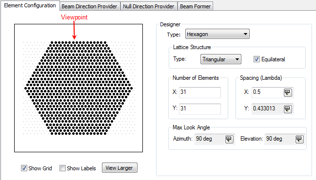
Element Configuration Viewport
The Element Configuration consists of element grid points, and each grid point has a unique ID number. Not all Element Configuration Types provide grid points other than the original element positions. You can enable or disable grid points to represent failed elements, to represent eliminated elements due to physical obstructions, or to model Minimum Redundant Arrays (MRA).
Select the Show Grid check box to display extra elements that can be enabled or disabled.
Select the Show Labels check box to display each unique element ID. This ID is important if you want to use an external file to assign complex weights to each element. See ASCII Data Element Configuration File for more information.
To enable or disable an element, click the element's grid point.
When you use an ASCII Data Element Configuration file, the Viewport will show the element configuration but will not allow you to enable or disable the elements.
Element Configuration Designer
The Designer enables you change the physical layout of the elements. Element configuration choices include the following:
When changing the type of configuration, number of elements, or the lattice structure, all disabled elements will be lost.
Lattice Structure
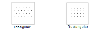
Lattice Structure selections only appear when you select Hexagon or Polygon for Designer Type. The elements are placed on a grid called a lattice structure. The lattice structure provides options for the general arrangement of the element placement. There are several options for the Lattice Structure of the element configuration. The type of lattice structure can be either triangular or rectangular. Selecting the Equilateral check box will enforce equal distance between the nearest neighbors.
| Parameter | Description |
|---|---|
| Triangular | Staggers the elements between rows and columns. |
| Rectangular | Aligns the elements between rows and columns. |
| Equilateral | For the triangular lattice structure, it will ensure the distance between all nearest neighbors are equal. For a rectangular lattice structure, it will ensure the distance in the X direction is equal to the distance in the Y direction. |
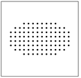
Polygon element configuration
This represents a two-dimensional planar antenna array with N sides. You can arrange the elements on either a triangular or a rectangular Lattice Structure. Furthermore, the polygon shape does not necessarily have to be a regular polygon. Thus, the number of elements in the X direction can be different than the number of elements in the Y direction.
| Parameter | Description |
|---|---|
| Number of Sides | Enter the number of sides of the antenna shape. |
| Lattice Structure | Provides options that determine the general arrangement of the element placement. |
| Type |
Choices vary depending on the selected Element Configuration Type: Triangular. Elements are placed in a triangular structure. Rectangular. Elements are placed in a rectangular structure. |
| Equilateral | Each element is equal in distance to its structural nearest neighbors. |
| Number of Elements |
X: Enter the number of elements in the X direction of the center row. Y: Enter the number of elements in the Y direction of the center column. |
| Unit Type | Unit Type defines the X and Y element spacing in either Wavelength Ratio or Distance units. The Wavelength Ratio unit type spaces the elements relative to the wavelength (e.g., Design Frequency). The Distance unit type spaces the elements at an absolute distance. |
| Spacing |
X: Enter the distance, in the unit type, between the elements in the X direction. Y: Enter the distance, in the unit type, between the elements in the Y direction. |
| Max Look Angle | See the Max Look Angle section below. |
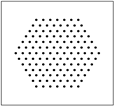
Hexagon element configuration
This is a six-sided specialization of Polygon. It is included primarily for your convenience. It represents a two-dimensional planar antenna array with an aperture shape consisting of six sides. Like Polygon, you can arrange the elements on either a triangular or a rectangular Lattice Structure. Likewise, the hexagon shape does not necessarily have to be a regular hexagon. Thus, the number of elements in the X direction can be different than the number of elements in the Y direction. However, for Hexagon, the number of elements in X and Y must be odd.
| Parameter | Description |
|---|---|
| Lattice Structure | Provides options that determine the general arrangement of the element placement. |
| Type |
Choices vary depending on the selected Element Configuration Type: Triangular. Elements are placed in a triangular structure. Rectangular. Elements are placed in a rectangular structure. |
| Equilateral | Each element is equal in distance to its structural nearest neighbors. |
| Number of Elements |
X: Enter the number of elements in the X direction of the center row (must be odd). Y: Enter the number of elements in the Y direction of the center column (must be odd). |
| Unit Type | Unit Type defines the X and Y element spacing in either Wavelength Ratio or Distance units. The Wavelength Ratio unit type spaces the elements relative to the wavelength (e.g., Design Frequency). The Distance unit type spaces the elements at an absolute distance. |
| Spacing |
X: Enter the distance, in the unit type, between the elements in the X direction. Y: Enter the distance, in the unit type, between the elements in the Y direction. |
| Max Look Angle | See the Max Look Angle section below. |
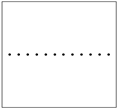
Linear element configuration
Represents an antenna array in one dimension.
| Parameter | Description |
|---|---|
| Num Elements | Enter the number of elements in the array. |
| Unit Type |
Unit Type defines the element spacing as either Wavelength Ratio or Distance units. The Wavelength Ratio unit type spaces the elements relative to the wavelength (e.g., Design Frequency). The Distance unit type spaces the elements at an absolute distance. |
| Spacing |
Spacing is the distance, in the unit type, between adjacent elements. |
| Tilt Angle | Enter the angle at which the array deviates from the X axis, with positive tilt being toward the positive Y axis (i.e., counterclockwise). |
| Max Look Angle | See the Max Look Angle section below. |
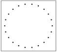
Circular element configuration
Represents a planar antenna array with elements arranged in a circular pattern.
| Parameter | Description |
|---|---|
| Num Elements | Enter the number of elements around the circle. |
| Unit Type |
Unit Type defines the element spacing as either Wavelength Ratio or Distance units. The Wavelength Ratio unit type spaces the elements relative to the wavelength (e.g., Design Frequency). The Distance unit type spaces the elements at an absolute distance. |
| Spacing |
Spacing is the distance, in the unit type, between adjacent elements. |
ASCII Data Element Configuration
An ASCII Data Element Configuration file enables you to define the number of elements and their placement through an external file. See the ASCII Data Element Configuration File topic for details and file format.
When you choose Type = Ascii Data and the number of elements in your file is 20,000 or greater, STK will display the message "Click here to show aperture elements" before attempting to redraw the elements in the viewport, since the redraw could take a while to process. If you click anywhere in the viewport, STK will redraw the element configuration.
Max Look Angle
The Max Look Angle fields contain informational parameters that identify the maximum steering angle that can be attained before grating lobes enter the antenna's view and cause ambiguities.
The maximum look angle does not restrict or constrain the simulation in any way and is not associated with any parameters associated with its parent.
When a transmitting antenna is steered beyond its maximum angle, then the antenna will produce maximum gain (and maximum radiation) in two different locations, one in the direction of the desired beam steering direction and the other in the direction of the grating lobe. Likewise, with a receiving antenna, it will have maximum reception gain in two different directions.
Beam Direction Providers
The Beam Direction Provider tab enables you to select where the antenna points its beam. This information is delivered to the beamformer, which handles forming and steering the beam toward the specified direction(s). The direction providers use a spherical Az/El coordinate system.
The following sections describe the Type selections for Beam Direction Providers — Object, Auto Pointing, ASCII Data, and Script — including the parameters associated with the Type choice.
Object Beam Direction Provider
Selects the beam pointing directions based on the STK object(s) you select. The antenna's direction provider supports Basic, Temporal, Analysis Workbench, Angle, and STK plugin constraints on the selected object. However, the STK application supports all Communications and Radar constraints on their respective Communications and Radar objects. When you select Type = Object on the Beam Direction Provider tab, you can set the following fields:
| Parameter | Description |
|---|---|
| Enabled | When you select this check box, the antenna will perform steering; otherwise, it will not. |
| Azimuth Steering Limit A | Relative to the mechanical boresight, electronically steering in the azimuth direction is bounded between this value and the value defined by AzimuthSteeringLimitB. The steering will be held at this value when attempting to steer beyond this value. |
| Azimuth Steering Limit B | Relative to the mechanical boresight, electronically steering in the azimuth direction is bounded between this value and the value defined by AzimuthSteeringLimitA. The steering will be held at this value when attempting to steer beyond this value. |
| Elevation Steering Limit A | Relative to the mechanical boresight, electronically steering in the elevation direction is bounded between this value and the value defined by ElevationSteeringLimitB. The steering will be held at this value when attempting to steer beyond this value. |
| Elevation Steering Limit B | Relative to the mechanical boresight, electronically steering in the elevation direction is bounded between this value and the value defined by ElevationSteeringLimitA. The steering will be held at this value when attempting to steer beyond this value. |
| When steering limits exceeded |
Determines the behavior of the beam steering when the direction of interest is outside the steering limits. Options include the following:
|
| Selection Filter | Select the check boxes next to individual objects to filter for just that type of object for the available object list below. Click to see all objects. Click to clear all the individual check boxes selected. |
| Object Selection |
STK software steers the antenna’s main lobe toward this object if the antenna has access to it. Click an object on the left to highlight it and then click A phased array antenna only has M-1 degrees of freedom, where M is the number of elements. If you also select a beam object, then the degrees of freedom are further reduced to account for the desired beam. Thus, STK software considers only the first M-1 list items and ignores the remaining ones. |
| Use mechanical boresight when zero Objects are in Field of Regard |
Determines the behavior of the beam pattern when there are zero directions of interest within the Field of Regard. When you select this check box, and there are zero directions (no access intervals for antenna and objects), the antenna will point along the mechanical boresight. When you clear this check box and there are zero directions (no access intervals for antenna and objects), the antenna will have no gain pattern and thus a no-gain value (i.e., antenna is turned off). |
| Max Selection Count | Specify the maximum number of targets to steer a beam toward. The number of beams generated will be less if the number of in-view targets is less than this maximum. |
| Selection Method |
Choose one of the following methods to determine which targets, up to the Max Selection Count, to select for beam steering: Range Selection Method - Selects targets based on the minimum range to each of the targets that are in view at each time step. Closing Velocity Selection Method - Selects targets based on the maximum closing velocity of each of the targets that are in view at each time step. The closing velocity is the target's velocity component in the direction of the phased array antenna. Priority Selection Method - Selects targets based on a user-defined priority value for each target instance. The lower the value, the higher the priority, with 0 being the highest priority. The lowest priority value is 1000, and this serves as the default for newly selected objects. At any given time step, when two or more objects in view have the same priority, the method will select targets based on their order in the list. |
Auto Pointing Direction Provider
The Auto Pointing Direction Provider is only available as a Beam Direction Provider. The Auto Pointing Direction Provider will steer the antenna’s beam toward the direction associated with the other object with an Access report. This option provides convenience when wanting to individually steer to different Access report objects because you don’t have to update the selected object within the Object Beam Direction Provider each time you run an Access Report.
The Auto Pointing option will disable 2D Graphics Contours and 3D Volume Graphics.
When you select Type = Auto Pointing on the Beam Direction Provider tab, you can set the following fields:
| Parameter | Description |
|---|---|
| Azimuth Steering Limit A | Relative to the mechanical boresight, electronically steering in the azimuth direction is bounded between this value and the value defined by AzimuthSteeringLimitB. The steering will be held at this value when attempting to steer beyond this value. |
| Azimuth Steering Limit B | Relative to the mechanical boresight, electronically steering in the azimuth direction is bounded between this value and the value defined by AzimuthSteeringLimitA. The steering will be held at this value when attempting to steer beyond this value. |
| Elevation Steering Limit A | Relative to the mechanical boresight, electronically steering in the elevation direction is bounded between this value and the value defined by ElevationSteeringLimitB. The steering will be held at this value when attempting to steer beyond this value |
| Elevation Steering Limit B | Relative to the mechanical boresight, electronically steering in the elevation direction is bounded between this value and the value defined by ElevationSteeringLimitA. The steering will be held at this value when attempting to steer beyond this value. |
| When steering limits exceeded |
Determines the behavior of the beam steering when the direction of interest is outside the steering limits. Options include:
|
Beam ASCII Data Direction Provider
See ASCII Data Direction Providers for information on this.
Beam Script Direction Provider
See Script Direction Provider for information on this.
Null Direction Providers
The Null Direction Provider tab enables you to select where the antenna points its null(s). This information is delivered to the beam former, which handles forming and steering the beam toward the specified direction(s). The direction providers use a spherical azimuth and elevation coordinate system. See spherical Az/El coordinate system for additional information. The Type choices for Null Direction Provider are the following: Object, ASCII Data, and Script.
Object Null Direction Provider
Selects the pointing directions for nulls based on your selection for STK Object(s). The antenna’s direction provider supports basic, temporal, vector, special, and STK plugin constraints on the selected Object. STK also supports all Communications and Radar constraints on their respective Communications and Radar objects. When you select Type = Object on the Null Direction Provider tab, you can set the following fields:
| Parameter | Description |
|---|---|
| Enabled | Select this check box to have the antenna perform null steering. |
| Azimuth Steering Limit A | Relative to the mechanical boresight, electronically steering in the azimuth direction is bounded between this value and the value defined by AzimuthSteeringLimitB. The steering will be held at this value when attempting to steer beyond this value. |
| Azimuth Steering Limit B | Relative to the mechanical boresight, electronically steering in the azimuth direction is bounded between this value and the value defined by AzimuthSteeringLimitA. The steering will be held at this value when attempting to steer beyond this value. |
| Elevation Steering Limit A | Relative to the mechanical boresight, electronically steering in the elevation direction is bounded between this value and the value defined by ElevationSteeringLimitB. The steering will be held at this value when attempting to steer beyond this value. |
| Elevation Steering Limit B | Relative to the mechanical boresight, electronically steering in the elevation direction is bounded between this value and the value defined by ElevationSteeringLimitA. The steering will be held at this value when attempting to steer beyond this value. |
| When steering limits exceeded |
Determines the behavior of the null steering when the direction of interest is outside the steering limits. Choose one of the following:
|
| Selection Filter | Select the check boxes next to individual objects to filter for just that type of object for the available object list below. Click to see all objects. Click to clear all the individual check boxes selected. |
| Object Selection |
STK steers the antenna’s null toward this object if the antenna has access to it. Click an object on the left to highlight it and then click A phased array antenna only has M-1 degrees of freedom, where M is the number of elements. If you also select a beam object, then the degrees of freedom are further reduced to account for the desired beam. Thus, STK considers only the first M-1 list items and ignores the remaining ones. |
Null ASCII Data Direction Provider
See ASCII Data Direction Providers for information on this.
Null Script Direction Provider
See Script Direction Provider for information on this.
Beamformers
The Beamformer tab enables you to select one of several beam/null forming methods, which in conjunction with the direction from the Beam/Null Direction Providers, computes the complex weights for each of the elements. STK software can then use these weights to compute the antenna’s gain pattern.
There are two categories of beamformers: those that perform beam steering and those that perform beam steering and adaptive null steering. The beamformers that do not perform adaptive nulling will implement an amplitude tapering to reduce the side-lobe levels. Amplitude tapering only applies to Element Configurations that are linear arrays. However, the Script Beamformer and ASCII Data Beamformer file beam formers provide the ability to specify a custom complex weight value.
The following sections describe the possible beamformer types, depending on the array configuration.
Uniform beamformer
This algorithm produces an amplitude distribution of unity across the elements.
Dolph-Chebyshev beamformer
This algorithm changes the phase and amplitude across the array elements to steer and shape the beam. It produces an amplitude distribution to achieve a minimum null-to-null beam width for a specified sidelobe level. The Dolph-Chebyshev beamformer will produce the optimal solution when spacing is >=wavelength/2. Setting the sidelobe level input to its most negative value (no sidelobes) will approach the binomial distribution. For more information, see the reference [“Antenna Theory Analysis and Design” Constatine A. Balanis, pp. 245 – 254]. This beamformer is only available for linear arrays.
| Parameter | Description |
|---|---|
| SidelobeLevel | Enter the desired sidelobe level on max gain. |
Taylor beamformer
Since the Dolph-Chebyshev beamformer entails all sidelobes having a user-specified level, it is not realistically attainable. The Taylor beamformer approximates the Dolph-Chebyshev beamformer by attempting to hold a user-specified number of sidelobes close to the user-specified sidelobe level and allow remaining sidelobes to be unconstrained, which is realizable. The sidelobe count (also called nbar) is the number of sidelobes on each side of the main lobe. As the sidelobe count increases toward infinity, the resulting pattern will approach Dolph-Chebyshev. Depending on the sidelobe count for a given sidelobe level, not all sidelobe levels are achievable. This beamformer is only available for linear arrays.
| Parameter | Description |
|---|---|
| SidelobeLevel | Enter the desired sidelobe level on max gain. |
| SidelobeCount | Enter the number of sidelobes from the main lobe that are nearly at the SidelobeLevel setting. This must be an integer greater than zero. |
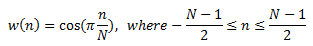
Cosine beamformer
This algorithm changes the phase and amplitude across the array elements to steer and shape the beam. It provides a cosine amplitude distribution across the array to reduce the sidelobes at the cost of slightly increasing the width of the main lobe. This beamformer is only available for linear arrays.
The amplitude distribution is given by:
Cosine^x beamformer
This algorithm changes the phase and amplitude across the array elements to steer and shape the beam. It uses an exponential form of a cosine function to reduce sidelobe levels at the cost of slightly increasing the width of the main lobe. This beamformer is only available for linear arrays.
The amplitude distribution is given by:
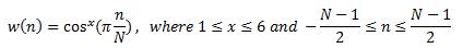
| Parameter | Description |
|---|---|
| x | Value of the cosine’s exponential. |
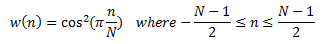
Hann beamformer
This algorithm changes the phase and amplitude across the array elements to steer and shape the beam. It utilizes aspects of the uniform and the cosine-squared pattern to place a null near a sidelobe peak. This beamformer is only available for linear arrays.
The amplitude distribution is given by:
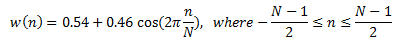
Hamming beamformer
This algorithm changes the phase and amplitude across the array elements to steer and shape the beam. It utilizes aspects of the uniform and the cosine-squared pattern to place a null near a sidelobe peak. This beamformer is only available for linear arrays.
The amplitude distribution is given by:
Raised Cosine beamformer
This algorithm changes the phase and amplitude across the array elements to steer and shape the beam. It combines aspects of the uniform and cosine weighting. The height of the first sidelobe will decrease by decreasing p. This beamformer is only available for linear arrays.
The amplitude distribution is given by:
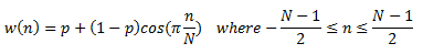
| Parameter | Description |
|---|---|
| p | Input parameter characterizing the weighting family as shown in above equation. |
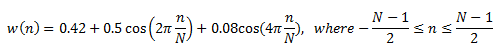
Raised Cosine-Squared beamformer
This algorithm changes the phase and amplitude across the array elements to steer and shape the beam. It is like the Raised Cosine, except for the cosine being squared. A parameter, p, value of 0.08 is equal to the Hamming beam former. This beamformer is only available for linear arrays.
The amplitude distribution is given by:
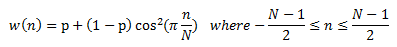
| Parameter | Description |
|---|---|
| p | Input parameter characterizing the weighting family as shown in above equation. |
Blackman-Harris beamformer
This algorithm changes the phase and amplitude across the array elements to steer and shape the beam. It implements the well-known Blackman-Harris distribution across the elements. This beamformer is only available for linear arrays.
The amplitude distribution is given by:
MVDR
Minimum Variance Distortionless Response (MVDR) is also referred to as a Capon beam former. It changes the phase and amplitude across the array elements to steer and shape the beam as well as the nulls. This performs adaptive beam forming to minimize the gain degradation in a desired direction while minimizing the gain in other directions. For more information, see the reference [“Optimum Array Processing Part IV of Detection, Estimation, and Modulation Theory” Harry L. Van Trees, p. 439].
| Parameter | Description |
|---|---|
| Constraint | Enter the value to constrain the amount of main gain reduction, which can take place to null interference. |
Custom Taper File Beamformer
Use this to specify a time-dependent taper (element amplitudes) in a text file. Each weight specified in the file is matched to an element by means of the element ID. Thus, the file’s element ID must match the element ID as specified in the antenna’s element configuration.
This differs from the ASCII Data Beamformer in that the Custom Taper File will only change the amplitude. Thus, the beam will still be steered based on the Beam Direction Provider. In contrast, for the ASCII Data Beamformer, you specify both the amplitude and phase. This means the ASCII Data Beamformer will not steer unless steering is designed in the complex weights.
If the first character of a line is '#', the entire line is treated as a comment line. Uncommented file lines have the following meanings:
- The first uncommented line is the file format version (required), which tells STK the format of the remaining file.
- The second uncommented line is a sampling mode (required). You can only use "SampleAndHold".
- The third uncommented line defines the format of the element weight data.
- The fourth uncommented line is the number of elements (required).
The remaining uncommented lines are time-specified complex element weights (required) with the following format:
<time> <element 1 id> <element 1 complex weight> ... <element n id> <element n complex weight>
where element IDs MUST correspond to the ENABLED element ID specified in the Element Configuration and the complex weights are specified as a comma-separated real and imaginary values enclosed in parentheses.
Here is a sample file for the Custom Taper File Beamformer:
#My sample Custom Taper Beamformer file
CustomTaperFileBeamformer v1
SampleAndHold
5
-1.0E300 0 (0.37464739463368862) 1 (0.79115929021973885) 2 (1.000)  3 (0.79115929021973885) 4 (0.37464739463368862)
10.0     0 (0.16785218258752427) 1 (0.68214781741247588) 2 (1.000)  3 (0.68214781741247588) 4 (0.16785218258752427)
1.0E300  0 (0.16785218258752427) 1 (0.68214781741247588) 2 (1.000)  3 (0.68214781741247588) 4 (0.16785218258752427)
ASCII Data Beamformer
See the ASCII Data Beamformer File topic for more information on this.
Script Beamformer
See Script Beamformer for more information on this.
Minimum Redundant Arrays
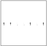
You can use the Phased Array Model to model Minimum Redundant Arrays (MRA). By exploiting unique element spacing combinations, you can remove elements. In doing so, an MRA can provide the same main beam characteristics with fewer elements, thus reducing the cost of the antenna. However, the side lobe levels will increase. There can be many combinations of MRAs for a given number of elements. As an example, by starting with a seven-element array and disabling three elements such that the spacing between each enabled element is unique, you can get a 1-3-2 MRA, where 1-3-2 indicates the element separation between each of the enabled elements.
Phased Array Antenna coordinate system
The Phased Array Antenna uses a spherical Az/El coordinate system referenced from the mechanical boresight. The mechanical boresight is aligned with the X axis when the Antenna’s Orientation Azimuth and Elevation values are both set to 0 degrees. STK defaults the Antenna’s Orientation Elevation value to 90 degrees to align the boresight with the Z axis. The elements of a linear array are aligned along the X axis when the tilt angle is 0. For rectangular arrays, the elements are located in the X-Y plane.