Cosine Squared Aperture Rectangular Antenna
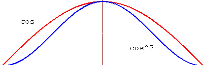
Cosine squared curve distribution pattern, with a rectangular pattern of illumination, illustrated by the blue curve below.
The gain pattern computations are based on the Cartesian Coordinate frame. The XY plane is the plane of illumination and the Z axis is the direction of the propagation.
Computing Gain Pattern Values
For a rectangular aperture antenna, the gain pattern values are computed on a unit sphere. STK computes and applies a gain factor. This gain factor computation is based on the aperture type, which eliminates the gain pattern anomalies observed at higher elevation angles off the antenna boresight. Refer to the reference below for details.
You can set the maximum gain value or let STK compute the gain pattern directivity factor value. STK uses a directivity factor to compute the maximum directivity along the boresight. The directivity factor is based on the aperture illumination type. For more information, see the reference below.
Note that you can override the directivity factor computed by STK.
If you specify a maximum gain value, this value is used to scale the overall antenna gain pattern.
Balanis, Constantine, Antenna Theory: Analysis and Design, New York: Wiley (1982), pp. 690-694.
Antenna Parameters
| Parameter | Description |
|---|---|
| X/Y Dimension |
The X Dimension and Y Dimension of the antenna size. Valid if Use Dimensions is selected. The beamwidths will be automatically calculated and displayed. |
| X/Y Dim Beamwidth | The X Dim Beamwidth and Y Dim Beamwidth of the antenna gain pattern. Valid if Use Beamwidth is selected. The dimensions will be automatically calculated and displayed. |
| Design Frequency |
Read-only field that displays the frequency inherited from the antenna's parent object (receiver, transmitter or radar), which is used in deriving 3dB beamwidth(s) from diameter or dimensions and vice versa. Frequency value must be changed before opening the details panel to use for gain calculation. For a communications receiver or transmitter, Design Frequency is set in the Single Beam Antenna window or, in the case of multibeam models, in the Modify Antenna Beam window. For a radar, it is set on the System page under Basic properties. A default value is used for retransmitters. |
| Main-lobe Gain | The main-lobe gain value. Valid if Computed is not selected. Select Computed to automatically calculate the main-lobe gain based on beamwidth or diameter, efficiency, and design frequency. |
| Efficiency | The antenna efficiency factor, ranging from 0 to 100 percent. |
| Back-lobe Gain |
You can use back-lobe gain two different ways:
|