EOIR provides the ability to use custom 3D meshes for objects using an OBJ (*.obj) file. The OBJ file format provides a simple subset of capabilities that represent very flexible, low-polygon, 3D geometry that EOIR renders with all the additional physics-based effects. However, if your 3D models are in other formats, or have very high polygon counts, there is a conversion and/or decimation process to reduce the number of polygons to a smaller level. Both of these can be achieved with the free 3D tool, Blender.
When using Blender it is easy to create new 3D geometry, decimate larger models into smaller models, and export to other file formats, such as OBJ files. This tutorial focuses on a few of these basic work flows that show how to use Blender to convert models.
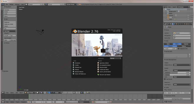
The images in this tutorial are from Blender version 2.75. Blender opens up with a splash screen and a default scene. For the latest version of Blender, see www.blender.org.
Change the Units in Blender
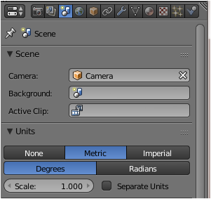
Since STK's default units are in meters, you need to set the units to meters in Blender.
- In the Scene Properties panel, set the units from None to Metric.
- Save a Startup file using Ctrl + U.
Blender Navigation
- Learn how to navigate a scene using these three mouse operations:
- Get comfortable manipulating what you have in a scene. Here are the most important object manipulating operations:
| Option | Value |
|---|---|
| Zoom | Use the mouse wheel |
| Rotate | Use the click wheel on the mouse and move the mouse around |
| Pan | Use the click wheel on the mouse while holding the Shift key and move the mouse around |
| Option | Value |
|---|---|
| Select | Right-click |
| Multi-select | Shift + Right-click |
| Select All or Deselect All | A |
| Move or Grab an Object | G and move the mouse around |
| Scale an Object | S and move the mouse around |
| Rotate an Object | R and move the mouse around |
| Cancel a Manipulation in Progress | Esc |
| Delete an Object | X |
| Undo | Ctrl + Z |
| Quad View | Ctrl +Alt+Q |
| Center the pointer | Shift + C |
| Switch between wire frame and solid frame | Z |
Blender Help can be found here http://www.blender.org/manual/
Object Interaction
- Now do some basic object interactions, such as moving and manipulating the default cube in the scene. It is important to fine-tune a scene before proceeding. To do this, you will need multiple view windows of your scene.
- Split the view into a quad view using Ctrl+Alt+Q.
- You can click the Z-key to change from the Solid Model View to a Wire Frame View.
- When loading your own custom model, if it does not display with the desired orientation you may select one or more views to adjust the orientation windows.
- To select the views you would like to adjust, use the R key to rotate the object around the Z or Y axis.
- Click the R key again to rotate around all axes.
- To select everything or a particular piece at a time and rotate it with R in the Top or Front view to only rotate about the Z or Y axis, respectively. To rotate about the X-axis, use the Right view.
- To apply modifications with a bit more finesse, hold the shift key while moving your mouse to slow things down or type in a number to scale, rotate, or move by a specific amount. You can also select the object and click N. You can see and modify your currently selected objects location, rotation, and scale parameters (click N again to hide this panel).
- To limit a move, scale, or rotation to a single axis, click the G, S, or R and move your mouse along the axis of your choice and hit the middle-mouse button. That will lock your operation to that axis and is helpful in a lot of modification situations where you just want to make things taller or carefully align things.
- Make sure to use Ctrl+A to reset any transformations.
We will go over more on axis alignment later.
Importing Files
- To load, decimate, and save 3D models as OBJ files, clear out what is in your scene.
- Click the A and the X buttons to delete all of the objects in the scene.
- With your cleaned-out workspace, you can now import models. To import models, Extend the File menu and select Open, if you happen to have a Blender formatted object, or Import, if you have another format or a higher resolution model.
- If importing an STL file, select to the Blender User Preferences panel and click Ctrl+Alt+U in the Add-ons section under Import-Export Then activate the STL plug-in.
- Save your user settings.
There is a set of importers that Blender comes with by default, and many other importing functions are available as 3rd party plugins.
Import the Satellite Sample File
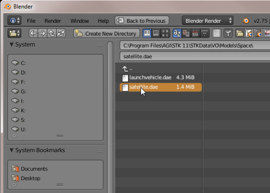
- As a sample file for this tutorial, browse to the STK install folder, which on a PC is <STK install folder>\STKData\VO\Models\Space.
- Import the satellite.glb file.
- Mouse around the scene and look at the object to make sure it loaded correctly. With the cursor over the OpenGl window, press the N key to bring up the "Numeric" panel.
- Switch to a solid view by using Z.
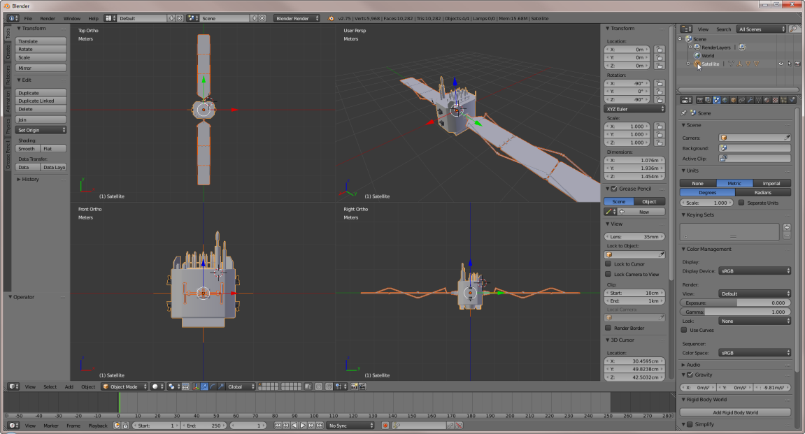
- In the Outliner panel, select the layer named Satellite. Looking at the Numeric tool bar, you should notice that the model has been rotated 90 degrees about the X and Z axis.
- Position the cursor back over the OpenGl window and press the A key twice, once to clear the bus and then once again to select all layers.
- Click Ctrl+A to reset the rotational values for this satellite.
Joining Multi-Part Objects
Some models that you import may have more than one part. For decimation purposes, models are easier to deal with if it has been collapsed down into one Layer, Component or Assembly.
- If you click the tiny Plus sign of the first layer in Outliner panel, it will expand the hierarchical tree structure so that you will be able to see the Solar_Panels. Expanding that layer will reveal two other layers.
- To join these three objects, place the cursor over the OpenGl window and hit "A" to select all.
- Next click Ctrl+J to join them all together.
It appears that the "Solar_Panels" didn't join with the rest, but no worries, that is just a left-over Null or Locator and can be ignored.
Decimating the Model
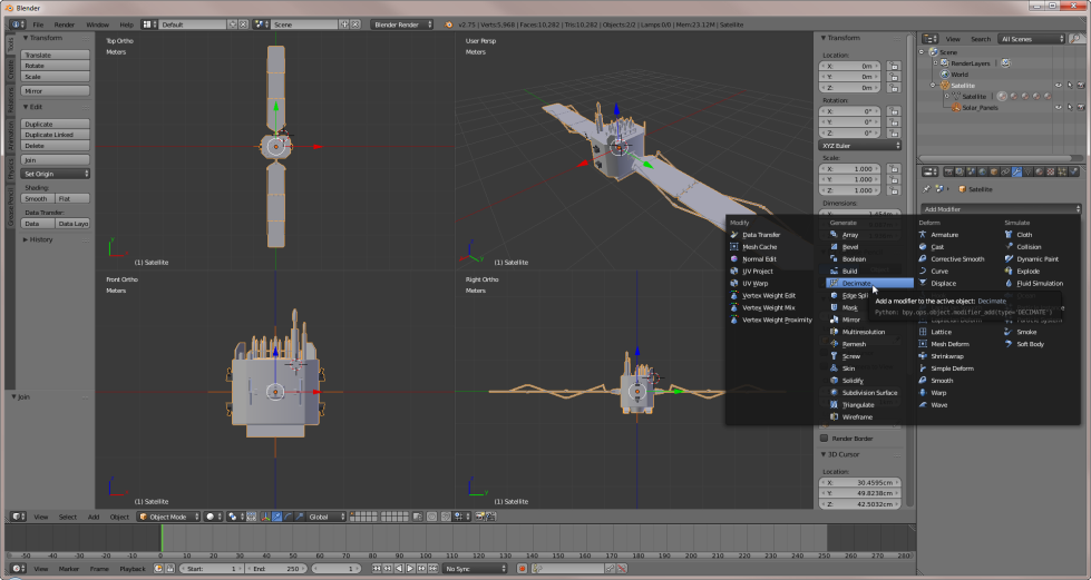
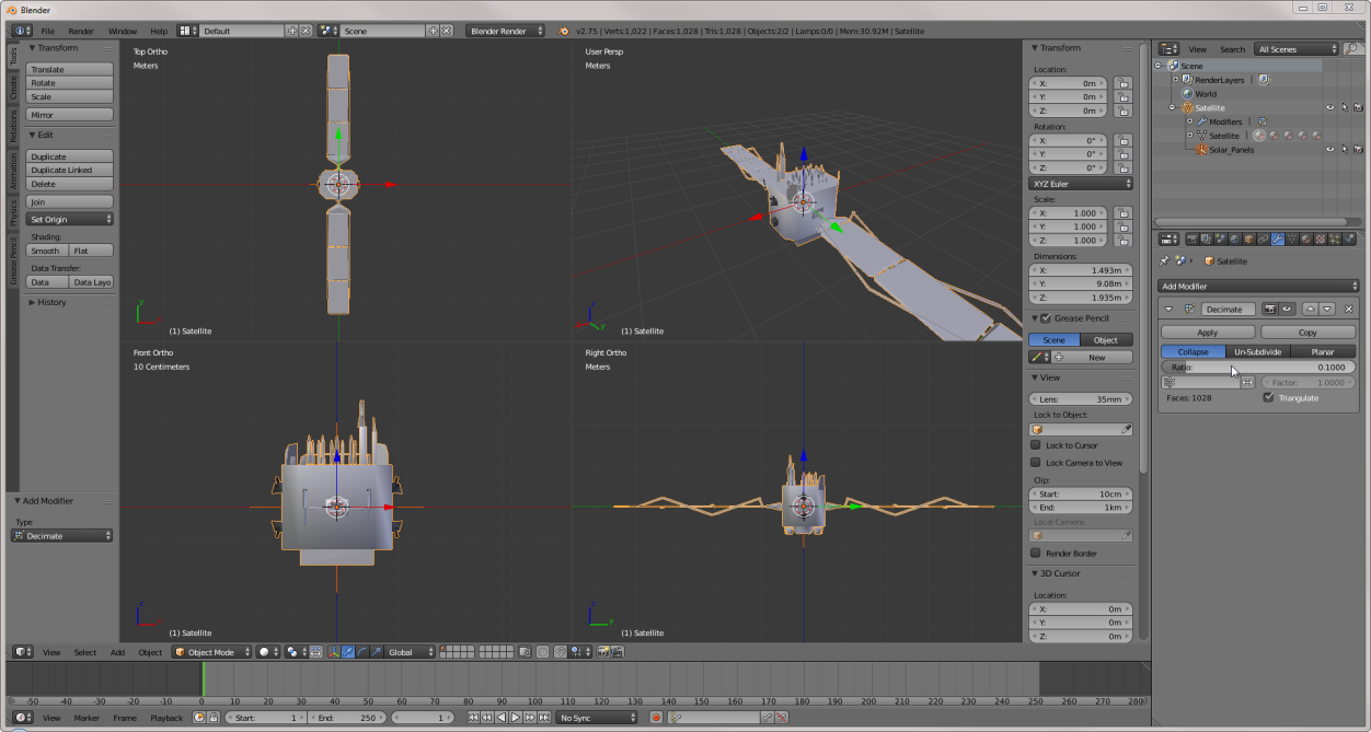
- Reduce the number of polygons as much as possible so that it will be able to load into EOIR and render quickly. With your object selected in the 3D window, in the Properties panel select the Object Modifiers menu option. Then under the Add Modifier option, select Decimate.
- Decimate shows the face count of your object, which is the number of polygons that you want to minimize so that your object still looks OK but in as few polygons as possible. Look at the Face Count, which currently stands at 10282 polygons and try modifying the different decimation options, taking a look around the model,. Take a moment to adjust this value to a minimum that you are happy with while also trying to get the face count as low as possible (for EOIR, below 1,000 polygons is optimal). With this example, changing the Collapse ratio to 0.1 keeps the important body structure modeled well enough but has reduced the face count from 10282 to 1028, a 90% reduction.
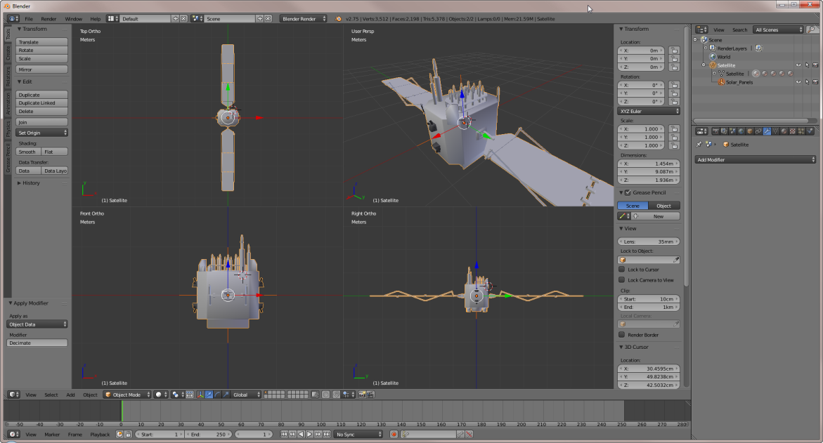
- Apply the changes when you are happy with your model’s new smaller face count,
Axis Alignment
Depending on the type of object to be imported into EOIR, the axis alignment for some types will be different.
| Option | Axis Alignment |
|---|---|
| Aircraft | X is aligned with the nose of the aircraft Z axis points nadir |
| Satellite |
X is aligned with the velocity vector Z axis points nadir |
| Ground Vehicle | X is aligned with the front of the vehicle Z axis points to zenith |
| Facility | X is aligned with the front of the building Z axis points to zenith |
| Launch Vehicle | X is aligned with the front of the nosecone Z axis points to zenith |
| Missile | X is aligned with the front of the missile Z axis points to zenith |
| Ship | X is aligned with the front of the bow Z axis points to zenith |
As for this model, no changes are needed, but if you are importing your own model, make sure to check the alignment. When finished, use Ctrl+A to reset all transformations.
Export to OBJ
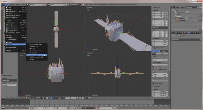
Now you are ready to export the new model as a OBJ file. With your object or objects selected, go to File and Export and choose the Wavefront OBJ file format.
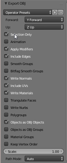
Modify the export options to match the snapshot below.
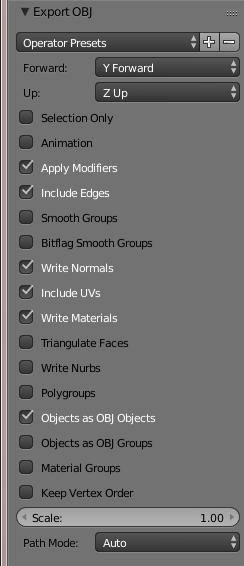
You now have a newly exported OBJ file that can be read by EOIR.
For more detailed information on converting model files for STK using Blender, see "How do I convert my model to MDL?" FAQ. You can get to this FAQ from support.agi.com.
Multi-Material Export
Materials associated with objects imported into Blender, that are intended for use in EOIR, are of no value, as they will be ignored upon import. This is why we aren't dealing with them in this tutorial. You will assign custom materials to each part in EOIR.
To analyze a model in EOIR that requires multiple materials, separate the model into each material group and save them out as separate OBJ files. In EOIR, this involves loading several files. Each file will have the same attitude and ephemeris.
Each part should have the material name included in the file name of the exported OBJ file. This will let you more easily associate a custom material to your part in EOIR.
Let's separate the solar arrays from the body of our present model. The entire model should still be selected.
If you accidentally delete your model, click CTRL + Z to undo it.
- Switch to a single view using "Ctrl+Alt+Q.
- On the numeric keypad, press the seven (7) key to go into a top view and then five (5) to change to an Ortho view. If you get lost, press the ESC key to return to the 3D View.
- Make sure that the entire model fills the windows. Hint: Use the decimal point on the numpad.
- Click the Z key to go into wireframe mode.
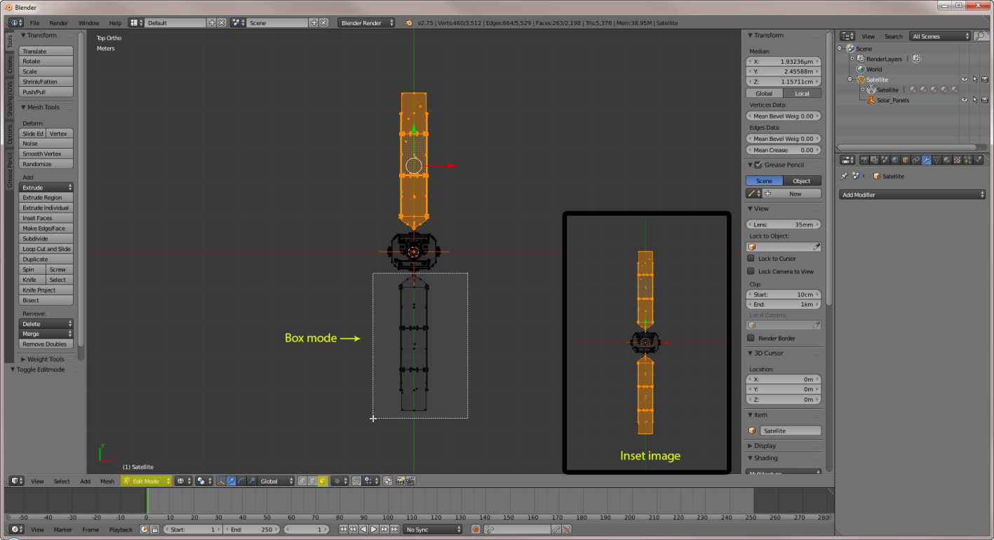
- Click the Tab key to go into Edit mode. (Highlighted in yellow below)
- Change the selection type from Vertex Select to Face Select.
- Using the Top view, click the B key to go into box select mode and select the majority of one of the arrays.
- Repeat the steps above to select another array.
- Click the B key again and select the other array.
- Click Ctrl+L to select any remaining linked geometry.
Now that we have the panels selected, we need to separate them from the bus so that we can save out a model of just the arrays.
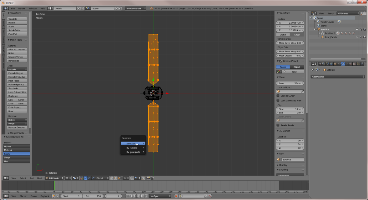
- Click the P key to separate the arrays and place them in there own layer.
- Tab out of "Edit" mode and take a look at the "Outliner" window.
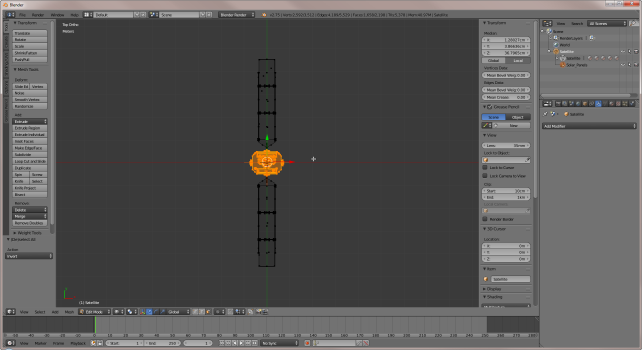
- In the Outliner panel, select just the arrays. They will be highlighted in yellow once again.
- 4. Include a step that changes a piece of the satellite, that way the model is unique to the standard satellite.dae file.
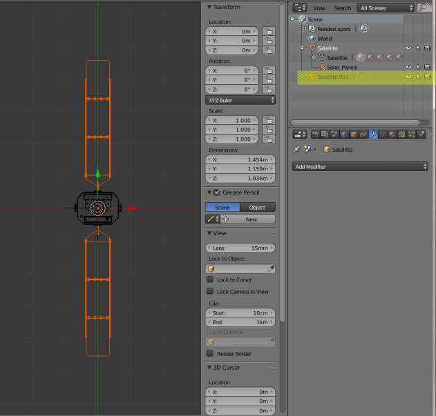
The arrays are highlighted in orange because multiple items were automatically selected after the operation.
Export the File
- Select the File_Export_Wavefront (.obj) menu and select the Selection Only option.
- Save the arrays with a name that reflects the custom material assigned to them in EOIR. An example would be, "satellite-arrays-aluminum.obj"
- Select the layer containing the bus and save a second OBJ file of just the body. Make sure that you give it an appropriate naming convention, based on the material that is to be assigned.