Target Signature file (.tsf)
The target signature file describes the intensity of an object. The intensity can vary temporally, spatially, and spectrally. The format of spectral intensity is Intensity<space>Wavelength<space>Value. Within the file, the separations between Intensity, Wavelength, and Value can be either spaces or tabs.
STK's EOIR capability will perform linear spectral interpolation of intensity between wavelength samples.
| Parameter | Required | Units | Description |
|---|---|---|---|
| Time | No | Epoch Seconds | This is the scenario time in epoch seconds. |
| Rho | No | Degrees | The Rho ( ) angle is the angle off the reference axis starting from the axis specified in RhoFromAxis. The range is 0° through 180°. See the RCS reference for a definition of the Rho angle here. ) angle is the angle off the reference axis starting from the axis specified in RhoFromAxis. The range is 0° through 180°. See the RCS reference for a definition of the Rho angle here. |
| Theta | No | Degrees | The Theta ( ) angle is defined as the rotation around the reference axis starting from the axis specified in ThetaFromAxis.
The range is -180° through +180°. See the RCS reference for a definition of the Theta angle here. ) angle is defined as the rotation around the reference axis starting from the axis specified in ThetaFromAxis.
The range is -180° through +180°. See the RCS reference for a definition of the Theta angle here. |
| RhoAxis | No | none |
The orientation of Rho starts on this axis. The value options are:
|
| ThetaAxis | No | none |
The orientation of Theta starts on this axis. The value options are:
|
| Wavelength | No | Microns | This is the spectral wavelength sample in microns. |
| Intensity | Yes | Watts-per-Steradian-Micron | This is the spectral intensity of the object. |
Examples
Example of a temporally, spatially, and spectrally constant target signature
In this example, the intensity is always 100 Watts-per-Steradian-Micron at all times, in every direction, and over every spectral region.
INTENSITY 100
Example of a temporally varying target signature
In this example, the target has a spectral intensity of 0, at 0 epoch seconds, in every direction; however, this increases linearly up to a spectral intensity of 100 at 50 epoch seconds in every direction.
TIME 0
INTENSITY 0
TIME 50
INTENSITY 100
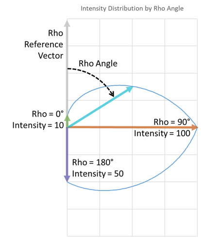
Example of a spatially varying target signature
In this example, the target has a spectral intensity of 10 directly in front, 100 to the side, and 500 directly behind the object. The relative intensity is symmetric about the target as the rho angle increases and is linearly interpolated with the angle.
RHO 0
INTENSITY 10
RHO 90
INTENSITY 100
RHO 180
INTENSITY 50
For this example, the relative intensity in each direction appears as shown here.
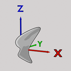
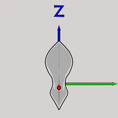
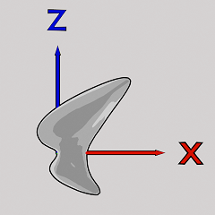
Example of a spatially varying target signature in both Rho and Theta
In this example, the target has an intensity of 10 in front and 0 behind. At the rho angles between, it has different values above and below the target, depending on the theta angle. The pictures show the axes with an example cloud image.
RHO 0
INTENSITY 10
RHO 45
THETA 0
INTENSITY 100
THETA 180
INTENSITY 50
RHO 90
THETA 0
INTENSITY 50
THETA 180
INTENSITY 25
RHO 180
INTENSITY 0

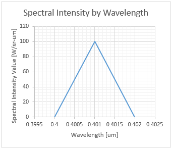
Example of a spectrally varying target signature
In this example, the target has a spectrally varying intensity with a spike centered on wavelength 0.401 microns and dropping to zero, one nanometer off to either side of the spectrum.
INTENSITY 0.400 0
INTENSITY 0.401 100
INTENSITY 0.402 0
The spectral intensity appears as a spike, as shown here.