Lambert Solver

Determining the impulse that produces the orbit connecting a departure state (position and velocity) with a later arrival point (position) is Lambert’s problem. The solution to this problem is well known, and various algorithmic approaches exist for implementing that solution. Lambert’s problem is inherently concerned with two-body orbital dynamics and requires a central body.

The Lambert Solver tool uses the methods detailed by Richard H. Battin, which is also used elsewhere within STK for ballistic propagation.

Battin, Richard H., An Introduction to the Mathematics and Methods of Astrodynamics, AIAA Education Series, AIAA, Inc., New York, 1987, pg. 258

Creating a Lambert Solver component

  1. Click the Utilities menu and select Component Browser....
  2. Select Design Tools in the list of components.
  3. Select the Lambert Solver component.
  4. Click Duplicate.
  5. Click in the Name or User Comment fields to customize them.
  6. Double-click the component to open the tool.

Defining the Lambert Solver component

To define the Lambert Solver, proceed using the following steps:

  1. In the Central Body field, click to select a central body.
  2. Both major modes of the tool require a central body. Central bodies that have no children are only valid if you are using the Specify initial and final states mode.

  3. In the Mode field, select the operating mode:
    • Specify initial and final central bodies - Specify the boundary states in relation to STK central bodies.
    • Specify initial and final states - Specify or import explicit position and velocity state variables.
  4. In the Solution Option field, select one of the following options:
    • Fixed time - Find the connecting solution consistent with the specified Time of Flight, if possible. This is the only option available for the Specify initial and final central bodies mode.
    • Minimum eccentricity - Find the solution associated with the fundamental ellipse.
    • Minimum energy - Find the transfer orbit with the smallest possible value for semimajor axis.
  5. In the Initial Epoch field, enter the time at which the initial state is defined. You can enter a specific value or select a time instant component from Analysis Workbench.
  6. If you are using the Fixed time solution option. enter the duration of the Lambert arc in the Time of Flight field.
  7. If you are using the Specify initial and final states mode with the Minimum eccentricity or Minimum energy solution options, you can select the Find Long Solution check box to solve for the Lambert arc that is consistent with the supplement of the default transfer angle.

Defining State or Central Body Properties

The remaining properties that you need to define are a function of the Mode.

Specifying the Initial and Final Central BodiesClosed

Departure Properties

    Field Description Interactions/Notes
    Body Select the central body to reference when specifying departure conditions. You can only select descendants of the tool-level Central Body. If the Central Body has no descendants, use the Specify initial and final states tool mode.
    Radius Specify a multiplier to specify the departure R magnitude for the departure body as the departure body’s radius.

    The departure body’s radius is taken as its maximum extension.

    If Radius = 0, the departure conditions are taken as the position and velocity of the departure body.

    If Radius > 0, the Depart from Circular Orbit option becomes available.

    Although circular departure orbits below the surface of the departing body are not usually desired, they are allowed.

    Altitude This is the difference between the R magnitude and the maximum extension of the departure body.

    This field is only for reference purposes.

    The associated value is approximated; it is not the detic altitude.

    Angle Enter the angle of the departure point in the velocity-normal plane, measured from the orbit normal of the Lambert arc. The velocity-normal plane is like the b-plane. For the definitions of the departure/arrival angles and velocity-normal plane, see the Lambert Velocity-Normal Planes and Special Body-to-Body Departure and Arrival Options section.
    Depart from Circular Orbit Select this check box to have the velocity conditions at the departure point (preimpulse) be consistent with a two-body circular orbit about the departure body.

    This option is available for departure radii > 0.

    The circular orbit shares the plane of the body-center-to-body-center Lambert solution.

    Consider Departure Body’s Gravity Select this check box to have the departure position rotated backward to periapsis of a hyperbola, and the preimpulse velocity is the circular velocity consistent with the departure position. The impulse for a hyperbolic departure from the departing body circular orbit is computed.

    This option is available for departure radii > 0 when the Depart from Circular Orbit check box is selected.

    Since the Delta-V to depart on the hyperbola is computed in the local gravity field of the departure body, the force model for later propagation of the result should include the departing body’s gravity.

    Arrival Properties

    Field Description Interactions/Notes
    Body Select the central body to reference when specifying departure conditions.

    You can only select descendants of the tool-level Central Body. If the Central Body has no descendants, use the Specify initial and final states tool mode.

    The arrival body may be the same as the departure body.

    Radius Specify a multiplier to specify the arrival R magnitude for the arrival body as the arrival body’s radius.

    The arrival body’s radius is taken as its maximum extension.

    If Radius = 0, the arrival conditions are taken as the position and velocity of the arrival body.

    If Radius > 0, the Insert into Circular Orbit check box is available.

    Although circular departure orbits below the surface of the departing body are not usually desired, they are allowed.

    Altitude This is the difference between the R magnitude and the maximum extension of the arrival body.

    This field is only for reference purposes.

    The associated value is approximated; it is not the detic altitude.

    Angle Specify the angle of the arrival point in the velocity-normal plane, measured from the orbit normal of the Lambert arc. The velocity-normal plane is like the b-plane. For the definitions of the departure/arrival angles and velocity-normal plane, see the Lambert Velocity-Normal Planes and Special Body-to-Body Departure and Arrival Options section.
    Insert into Circular Orbit Select this check box to have the velocity conditions at the arrival point (postimpulse) be consistent with a two-body circular orbit about the departure body. This option is available for arrival radii > 0. The circular orbit shares the plane of the body-center-to-body-center Lambert solution.
Lambert Velocity-Normal Planes and Special Body-to-Body Departure and Arrival OptionsClosed

When using the Specify initial and final central bodies mode, certain challenges occur when moving solutions from lower-fidelity to higher-fidelity regimes. To use the solutions for an Astrogator satellite, it is usually necessary that they be compatible with the higher-fidelity environment. For example, a common practice for body-to-body Lambert analysis is to inherit the departure and arrival bodies’ states as the boundary conditions for the Lambert problem. It is clear that such a solution, originating from a relative position of (0, 0, 0) in relation to the departure body, will not work when that body’s gravity is considered. Body-center-to-body-center use cases remain available in the Lambert Solver by setting the Departure and Arrival Radii to zero if desired. But, to streamline the workflow of transitioning solutions into Astrogator, more options have been provided.

The extra options for departure and arrival conditions are realized through a process that bootstraps from the body-center-to-body-center Lambert solution. The center-to-center Lambert solution represents a transfer orbit. From this preliminary transfer orbit, geometry is available to allow definition of departure and arrival states away from body centers.

Involved in the geometric relationships defining the departure and arrival states are planes normal to velocity vectors at these points; these planes are velocity-normal planes. The velocity-normal planes used for the Lambert Solver are like the b-plane, but reflect slight differences in definition that are useful to the Lambert Solver. The steps for defining the departure and arrival conditions illustrate the velocity-normal planes. These steps involve setting a radial position relative to the body center, aligning the radial direction in the velocity-normal plane, and augmenting the departure/arrival velocity as desired.

A few steps are taken to specify the radial displacement of the departure state. The cross product of the departure velocity and orbit normal associated with the body-center-to-body-center Lambert solution specifies the default radial displacement direction. The Lambert orbit-normal direction is required:

where 
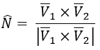
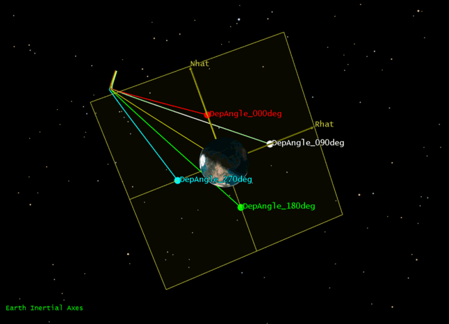
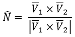
is the velocity on the Lambert orbit after the departure impulse and is the velocity on the Lambert orbit before the insertion impulse at arrival (both velocities are described in the departure body’s inertial frame). The 
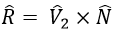
̂ direction is the default direction of radial displacement corresponding to a departure angle of 90°.

The velocity-normal plane and the 
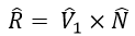
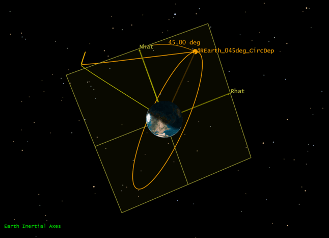
axes are depicted in Figure 1.

Figure 1: Departure velocity-normal plane and unit vectors

The Radius multiplier, r, is used in conjunction with the maximum extent of the central body’s surface, Rbody, to specify the magnitude of the radial extension 
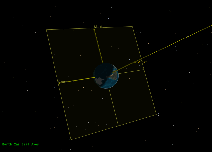
. The departure point is placed along the radial displacement direction at the specified magnitude. If the departure angle is 90°, the position of the departure point is fully defined .

The departure angle, α, adjusts the alignment of the departure position vector. The departure velocity-normal plane is spanned by the basis vectors , and the departure angle adjusts the position vector as measured in theplane in a right-hand sense about from . Thus, an angle of 90° is consistent with . Other choices of the departure angle result in alternate departure positions on the circle of radius Rmag in the plane, centered on the departure body.

As an example, several departure points of Radius = 2REarth at various departure angles are illustrated in Figure 2.


Figure 2: Various departure angles

More options are available to adjust the departure and arrival velocities (pre- and post-impulse, respectively). These options are the Depart from Circular Orbit and Insert into Circular Orbit options. Rather than use the departure/arrival bodies’ velocities to compute the Lambert impulses, the circular options define the initial/terminal velocities as those associated with circular orbits of the specified radii at the respective bodies. Figure 3 shows an example where the associated circular orbit was added to the satellite with a Backward Sequence preceding the Lambert solution.

Figure 3: Circular departure

A final option is available only for specification of the departure conditions. This option is the Consider Departure Body’s Gravity. When using this option, the conditions before insertion on the modified Lambert solution are mostly consistent with the preceding departure from circular orbit option. But, when considering the departure body’s gravity, a hyperbolic departure must be computed consistent with the Target Vector Outgoing Asymptote state associated with the Lambert departure as observed in the departure central body’s inertial frame. So, the departure point moves to periapsis on the departure hyperbola (“back-rotated” on the circular orbit by the true anomaly of the TVOA state). Figure 4 displays a solution where, again, the circular orbit has been added in a post-processing step within the resulting Astrogator satellite.

Figure 4: Considering departing body's gravity

The general definitions and concepts associated with the departure body also apply at the arrival body. But, the vectors used to define the arrival velocity-normal plane and associated directions are different. The velocity vector on the center-to-center Lambert orbit at arrival is used, and the orbit normal is now computed as before

but now with the velocity vectors taken in the arrival body’s inertial frame. The R direction upon arrival is taken as 
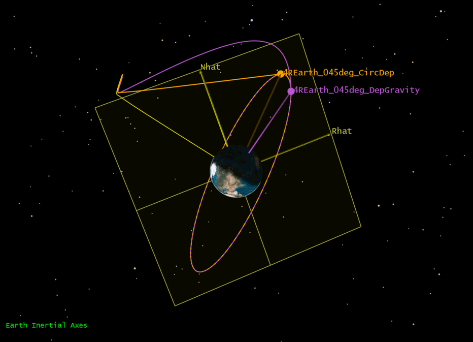
(everything in the arrival body’s inertial frame).

Specifying the Initial and Final StatesClosed

If you are using the Specify initial and final states mode, Astrogator expects the state variables as Cartesian variables in the Lambert tool’s Central Body Inertial reference frame. You can manually enter these values or click Set... to use the import utility. The import utility enables you to define the state variables in other reference frames and in Keplerian elements.

Initial State Properties

    Field Description
    Rx, Ry, Rz The Cartesian position vector components
    Vx, Vy, Vz The Cartesian velocity vector components

    Final State Properties

    Field Description
    Rx, Ry, Rz The Cartesian position vector components
    Vx, Vy, Vz The Cartesian velocity vector components
Import UtilityClosed

The import utility enables you to define the state variables in other reference frames and in Keplerian elements.

Import Utility Properties

Control Description Interactions/Notes
Frame Selector Use this field to select a reference frame associated with the state variables to import. You may use any reference frame valid at the import epoch.
Representation Selector Use this field to select the state variable representation associated with the state variables to import. Keplerian is only available for inertial reference frames.
Paste Format label Indicates the expected format and units of state variable data to be imported.  
Paste Box

Use this field to paste six state variables that are consistent with the format and units in the Paste Format label.

As long as you supply these six numeric values in the proper order and separated by white space (space, tab, carriage return), other characters are ignored.

Scientific notation is not required.

Epoch Label This field displays the epoch against which Astrogator will validate the import data.

For departure, this is the epoch specified as the Initial Epoch; for arrival, this is the offset from the Initial Epoch consistent with the specified Time of Flight.

Take care when using Solution Options other than Fixed Time and specifying final states in time-dependent reference frames.

Validate Click this button to attempt to parse the input data and convert it to CBI.  
Validation result label This section displays the outcome of the validation attempt. If successful, this label displays “Central Body Inertial” and the various position and velocity labels are populated with the converted values.
Accept Click this button to push the validated state values back into the initial/final states for use in the Lambert problem.  

Calculating and using the solution data

After defining all the Lambert Solver data, you can calculate and apply the solution. Click Compute . The Solution section displays relevant information for the calculated solution.

    Solution DataClosed

    The Solution box reports representative data that result from computing the Lambert solution. Some fields apply to specific workflows, while others apply regardless.

    Choice Description Notes
    Status label Indicates the result of the Compute operation

    Possible results include:

    • No valid solution computed
    • State to state solution
    • Body to body solution
    • Departure or arrival body not set
    Initial DeltaV The magnitude of the impulse required for the Lambert arc.  
    Final DeltaV The magnitude of the impulse required to match velocity with the arrival conditions.  
    Total DeltaV This is the sum of the Initial DeltaV and Final DeltaV.  
    Time of Flight The duration of the Lambert arc.

    If the selected solution is

    • Fixed Time: This should be consistent with the time specified in the Time of Flight field in the top-left section.
    • Minimum eccentricity/Minimum energy: This value is usually different from the Time of Flight field in the top-left section.
    Departure C3 The equivalent C3 energy to depart on the Lambert arc.

    This field applies to body-to-body solutions:

    • If the departure R magnitude is greater than 0, the C3 value is computed by converting the departure position and velocity (post-impulse) to Target Vector Outgoing Asymptote coordinates at the departure body.
    • If the departure R magnitude is 0 (a body-center departure condition), C3 is computed as Vinf^2 = (Initial DeltaV)^2.
    Departure RA The equivalent right ascension of the impulse to depart on the Lambert arc.

    This field applies to body-to-body solutions:

    • If the departure R magnitude is greater than 0, the RA value is computed by converting the departure position and velocity (post-impulse) to Target Vector Outgoing Asymptote coordinates at the departure body.
    • If the departure R magnitude is 0, RA is computed as the angle of the DeltaV vector in the departing central body’s inertial X-Y plane (measured from +X̂).
    Departure Dec The equivalent declination of the impulse to depart on the Lambert arc

    This field applies for body-to-body solutions:

    • If the departure R magnitude is greater than 0, the Dec value is computed by converting the departure position and velocity (post-impulse) to Target Vector Outgoing Asymptote coordinates at the departure body.
    • If the departure R magnitude is 0, Dec is computed as the angle out of the X-Y plane of the departing central body’s inertial frame (positive towards +Ẑ).

    If the Propagator Requires Departure Body’s Gravity label appears (found below the Solution section and above the Propagator for Sequence field), the solution was computed using the Consider Departure Body’s Gravity body-to-body option. When choosing the propagator for sequence construction, you should include the departure body’s gravity for best results.

    To use the solution results in a sequence, proceed with the following steps:

  1. In the Propagator for Sequence field, click to select the propagator for the resulting sequence.
  2. This is not used in the Lambert computation.
  3. In the Name for Sequence field, enter the name for the sequence. If left blank, the resulting sequence will be automatically named “Lambert Solution.” If this is the same name as an existing sequence, you can select the Replace Existing Sequence check box to override the existing sequence data with the new solution.
  4. Select the Auto Add to MCS Segments check box to automatically add the sequence to the MCS Segments Component Browser library after the sequence construction. If a component has the same name as another component, a digit is added to the most recent component consistent with existing Component Browser paradigms.
  5. If you plan on editing the sequence before you add it to the Component Browser, leave this check box cleared.

  6. Click Construct Sequence to construct an Astrogator Sequence segment containing an Initial State segment and a Target Sequence segment. The Target Sequence contains two Impulsive Maneuver segments and a Propagate segment.

Editing and adding segments

To manually edit the segments before adding them to the Component Browser:

  1. Click Edit Segments… . The Edit Segments window appears.
  2. Make your edits to the segments and then click OK .
  3. Click Add to MCS Segments to add the constructed sequence to the MCS Segments library.