Targeting Constraints
Targeting constraints, which you can find on the Constraints > Targeting page of an object's Properties window, enable you to define the geometrical extent of access between an object and the target of that object. Any listed targeting constraint not available for accesses from a particular object to a particular target will appear grayed out.
When applying targeting constraints, STK measures the location of the target object (often an object on the ground) relative to the central body-fixed (CBF) VVLH frame of a vehicle. STK computes the CBF VVLH frame using the vehicle's CBF position and velocity, with axes defined as follows:
- Z axis aligned with centric nadir (i.e., opposite to the position vector)
- Y axis opposite to the direction of the cross product of position with velocity
- X axis aligned with the tangential component of velocity (i.e., the velocity component perpendicular to the position vector)
In these axes, the cross-track direction is associated with the Y axis and the in-track direction is associated with the X axis. The terms cross-track and in-track for satellites are usually based upon the central body inertial VVLH frame, where velocity is measured with respect to inertial axes. However, for targeting constraints, STK uses the CBF VVLH frame.
Let V denote the vehicle's position vector, T denote the target object's position vector, and let the vector P denote the projection of the target object's position vector into the X-Z plane. The directions VPT form a spherical right triangle (with right angle at P), where the angle between V and P is the in-track angle and the angle between P and T the cross-track angle. The in-track angle is measured in the X-Z plane, while the cross-track angle is measured perpendicular to the X-Z plane.
STK associates a range with each angle by multiplying the angle (in radians) by the radius R_avg, which is the average distance to the vehicle's central body surface from its origin, along the V and T directions, calculated as:
R_avg = 0.5 *(R_Vp + R_Tp)
where
Vp locates the centric subpoint of the vehicle V.
R_Vp is the magnitude of Vp's position vector.
Tp locates the centric subpoint of the target object T.
R_Tp is the magnitude of Tp's position vector.
STK uses a sphere of radius R_avg to approximate the vehicle’s central body shape, for the purpose of computing distance along the surface between the directions V, P, and T.
When the vehicle is a satellite, the X-Z plane serves as a proxy for the plane tangent to the ground track. The ground track itself remains close to this plane near the satellite's centric subpoint, and so this plane is also a proxy for making measurements relative to the ground track itself. This is especially true for ground targets that are within line of sight to the satellite, since they are not too far forward or behind it.
The table below describes the Targeting constraints you can set and lists the objects that you can apply them to when generating access intervals.
When an access involves a child object (i.e., sensor, transmitter, receiver, antenna, or radar), use the child object's parent or grandparent in the table below to determine whether the constraint can be used for access to that child object. For example, if a constraint can be used for accesses to all vehicles, then that constraint can also be used for any child object of a vehicle.
In the following table, abbreviations in the Constraints used for accesses to... column are:
| F = facility | Pl = place | T = target | V = all vehicles | S = satellite | M = missile | L = launch vehicle | G = ground vehicle |
| A = aircraft | Sh = ship | Sn = sensor | AT = area target | LT = line target | P = planet | St = star |
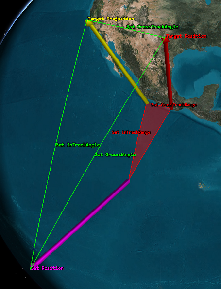
The following diagram illustrates the Cross Track Range and In Track Range targeting constraint options described above.
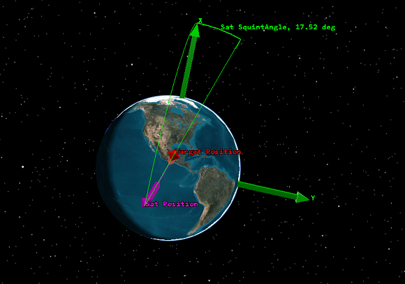
The following diagram illustrates the Squint Angle targeting constraint option described above.