Vector Geometry Tool (VGT) Reference Frames
This topic provides technical notes concerning common Vector Geometry Tool reference frames installed with STK.
All central bodies in the VGT support inertial axes, and except for Earth and Sun, these axes are identical to ICRF.
You can use any VGT coordinate system as the CoordinateAxes keyword in attitude (*.a) files and as the CoordinateSystem keyword in ephemeris (*.e) files. You can also use them as coordinate system options when defining the initial orbit state for Two Body, J2, J4, and HPOP propagators.
To expand all topics together, click  in the Help toolbar. To collapse all topics together, click
  again.
Central body-based reference frames
The VGT contains the following central body reference frames.
The ICRF axes are defined as the inertial (i.e., kinematically nonrotating) axes associated with a general relativity frame centered at the solar system barycenter (often called the BCRF). The IAU (International Astronomical Union) is the authority for the definition of the ICRF. The ICRF is the best realization of an inertial frame constructed to date and thus represents an improvement upon the theory behind the J2000 frame. While the ICRF and J2000 frames themselves are very close, they are not identical. Moreover, the J2000 frame rotates (very slowly) over time with respect to the ICRF frame. Recent star catalogs and celestial body ephemerides are most often expressed natively with respect to the ICRF frame.
The ICRF frame is realized by its transformational algorithm between it and the Earth Fixed frame. The current algorithm uses the P03 precession model, the IAU2006 nutation model, and the Earth rotation angle (expressed as a linear function of time in UT1) and became operational on 1 Jan 2009. There is no documentation available from IERS (the International Earth rotation and Reference systems Service) for the current operational model. AGI uses an implementation based upon code available from SOFA (Standards of Fundamental Astronomy), the same code used to produce values in the Astronomical Almanac. The IAU2006 nutation model and the Earth rotation angle are documented by IERS is its Technical Note No. 32, IERS Conventions 2003.
Within AGI products, the term "ICRF coordinate system" is not restricted to the system having its origin at the solar system barycenter. Rather, the term describes a coordinate system having an origin as determined from context (i.e., for a central body, its center-of-mass location) with axes aligned with the axes of the BCRF. In fact, the IAU uses the term GCRF to refer to the system with origin at the geocenter (i.e, Earth’s center-of-mass location), with axes parallel to the BCRF. The term "aligned" here refers to directions in Euclidean space, not in a curved space governed by general relativity.
Mean Equator and Mean Equinox of the J2000 epoch (JD 2451545.0 TDB, which is 1 Jan 2000 12:00:00.000 TDB). The J2000 axes were considered the best-realized inertial axes until the development of the ICRF. The J2000 frame is realized by the transformational algorithm (also known as the FK5 IAU76 theory) between it and the Earth's Fixed frame. The algorithm uses the 1976 IAU Theory of Precession, the 1980 Nutation model, and the Greenwich Mean apparent Sidereal Time (expressed as a function of time in UT1), updated by IERS Technical Note No. 21 to include an adjustment to the equation of the equinoxes.
Within AGI products, the term "J2000 coordinate system" is not restricted to the system having an origin at Earth’s center. Rather, the term describes a coordinate system having an origin determined from context (i.e., for a central body, its center-of-mass location), with axes parallel to the axes of the J2000 system defined at the Earth.
This represents central body-centered-fixed axes.
This is an alias for the Earth's Fixed frame. It is only available for Earth.
This represents central body-centered fixed axes of the J2000 epoch.
This represents central body-centered MOJ2000 axes.
MOJ2000 in the VGT is a particular instantiation of the MeanofEpoch coordinate system type in STK. In the VGT, the epoch is set to J2000 for this coordinate system.
This represents central body-centered TOJ2000 axes.
TOJ2000 in the VGT is a particular instantiation of the TrueOfDate coordinate system type in STK. In the VGT, the epoch is set to J2000 for this coordinate system.
This represents the True Equator Mean Equinox axes of the J2000 epoch.
TEME2000 in the VGT is a particular instantiation of the TEMEOfDate coordinate system type in STK. In the VGT, the epoch is set to J2000 for this coordinate system.
Sun system only
This is the True Equator True Equinox axes of Greenwich midnight.
MeanOfDate definition for all central bodies except Earth and Moon
This uses the same computation as TrueOfDate, except that when the Fixed frame Z axis is computed, any oscillatory terms in the formulas for the right ascension and declination are ignored.
MeanOfDate definition for Earth
This is the Mean Equator and Mean Equinox of date. The transformation between J2000 and MeanOfDate is computed using a sequence of Euler rotations. Rotation angles are computed using cubic polynomials of time past the J2000 epoch in JED according to the 1976 IAU Theory of Precession angles and rates, as found in the US Naval Observatory circular No. 163. The MeanOfDate Z axis is the Earth’s mean spin axis; the MeanOfDate X axis defines the mean vernal equinox.
MeanOfDate definition for the Moon
The Z axis aligns with the IAU2003 Z axis, and the X axis aligns with the vector that is the cross product of the ICRF Z axis and the IAU2003 Z axis, evaluated at each given time. However, when computing the IAU2003 Z axis, the oscillatory terms are ignored.
TrueOfDate definition for all central bodies except Earth and Moon
The Z axis aligns with the Fixed Z axis, and the X axis aligns with the vector that is the cross product of the ICRF Z axis and the Fixed Z axis, evaluated at each given time.
If the cross product is zero, then the Y axis aligns with the cross product of the Fixed Z axis and the ICRF X axis.
TrueOfDate definition for Earth
This is the True Equator and True Equinox of date. The transformation between Earth’s MeanOfDate to Earth’s TrueOfDate axes uses the mean obliquity, the nutation in longitude, and the nutation in obliquity, computed according to the 1980 Nutation model. It then applies the update to the equation of the equinoxes. By default, the nutation values are obtained by interpolating values contained in the JPL DE file rather than evaluating the model directly. The TrueOfDate Z axis is the Earth’s spin axis if pole wander is ignored; the TrueOfDate X axis defines the true vernal equinox.
TrueOfDate definition for the Moon
The Z axis aligns with the Fixed Z axis, and the X axis aligns with the vector that is the cross product of the ICRF Z axis and the Fixed Z axis, evaluated at each given time. The TrueOfDate frame is very close to the Mean Lunar Equator and IAU Node of Date (Lunar Constants and Model Document, JPL D-32296, Sept 2005). If the Moon’s Fixed frame were set to use the IAU2003 frame, then the two frames would be identical.
Earth System only
This is the True Equator and Mean Equinox of date. It is an intermediate frame associated with the transformation from Earth’s MeanOfDate to Earth’s TrueOfDate axes. The TEMEOfDate Z axis is aligned with the TrueOfDate Z axis; the TEMEOfDate X axis is close to (but not identical to) the MeanOfDate X axis.
Earth system only
This is the Earth's Fixed axes without accounting for pole wander.
Moon System only
Principal Axes (PA) System. The principal axes frame is aligned with the principal inertia axes, with the Z axis along the maximum inertia and the X axis along the minimum inertia. This is sometimes referred to as the axis of figure frame. The PA frame is developed in conjunction with the development of the ephemerides for the Moon. Hence, the frame depends on the source JPL DE file being used. The PA 403 frame is defined through the use of the JPL DE403 file. The PA 403 frame is realized based on a transformation from the ICRF frame based on Euler angles provided as part of the DE403, if you select DE403 at the application level as the planetary ephemeris source. If the application is configured to use a different DE version, then the 403 PA frame is realized as a constant rotation from the MeanEarth frame. The principal axis frame associated with the DE405 ephemeris is essentially identical to the 403 PA frame.
Moon System only
This is an alternative definition of the Moon fixed axes, IAU2003 axes, which is based on the formulation in the IAU 2003 report, and the principal (fixed) axes as defined in the DE data set DE421.
Moon System only
Principal Axes (PA) System. The principal axes frame is aligned with the principal inertia axes, with the Z axis along the maximum inertia and the X axis along the minimum inertia. This is sometimes referred to as the axis of figure frame. The PA frame is developed in conjunction with the development of the ephemerides for the Moon. Hence, the frame depends on the source JPL DE file being used. The PA 430 frame is defined through the use of the JPL DE430 file. The PA 430 frame is realized based on a transformation from the ICRF frame based on Euler angles provided as part of the DE430, if you select DE430 at the application level as the planetary ephemeris source. If the application is configured to use a different DE version, then the 430 PA frame is realized as a constant rotation from the MeanEarth frame.
The DE440 is the default Moon ephemeris.
Moon system only
Principal Axes (PA) System. The principal axes frame is aligned with the principal inertia axes, with the Z axis along the maximum inertia and the X axis along the minimum inertia. This is sometimes referred to as the axis of figure frame. The PA frame is developed in conjunction with the development of the ephemerides for the Moon. Hence, the frame depends on the source JPL DE file being used. The PA 440 frame is defined through the use of the JPL DE440 file. The PA 440 frame is realized based on a transformation from the ICRF frame based on Euler angles provided as part of the DE440, if you select DE440 at the application level as the planetary ephemeris source. If the application is configured to use a different DE version, then the 440 PA frame is realized as a constant rotation from the MeanEarth frame.
This is the default Moon ephemeris.
Trajectory-based reference frames
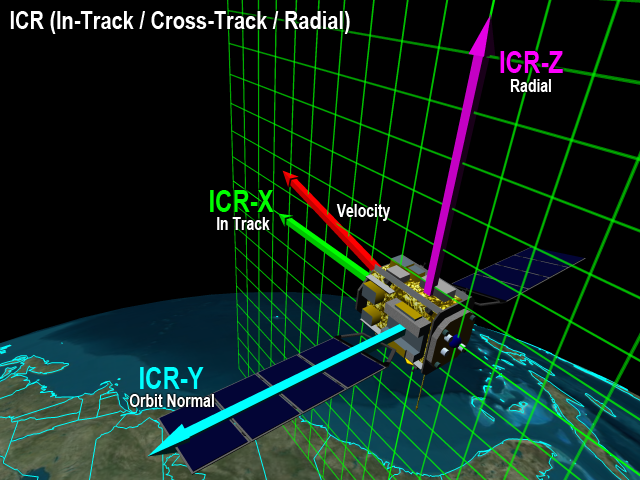
In-track / Cross-track / Radial (ICR) axes align the Z axis along the position vector (radial outward) and the Y axis along the orbit normal vector (cross-track). The axes are dependent on the object.
The orbit normal direction is defined as the direction of the cross product of the position vector with the inertial velocity vector; therefore, the in-track and radial axes lie in the orbit plane.
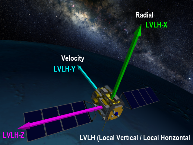
Local-Vertical Local-Horizontal axes align the X axis along the position vector and the Y axis toward the inertial velocity vector; these are dependent on the object.
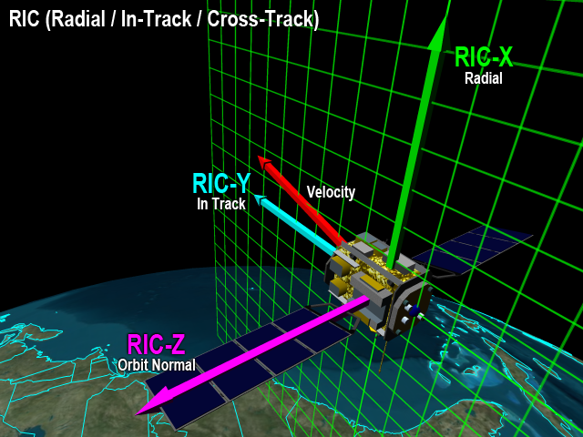
Radial / In-track / Cross-track axes align the X axis along the position vector and the Y axis toward the inertial velocity vector; these are dependent on the object.
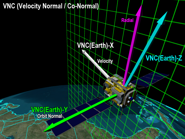
Velocity Normal Co-Normal axes align the X axis along the inertial velocity vector and the Z axis toward the position vector; these are dependent on the object.
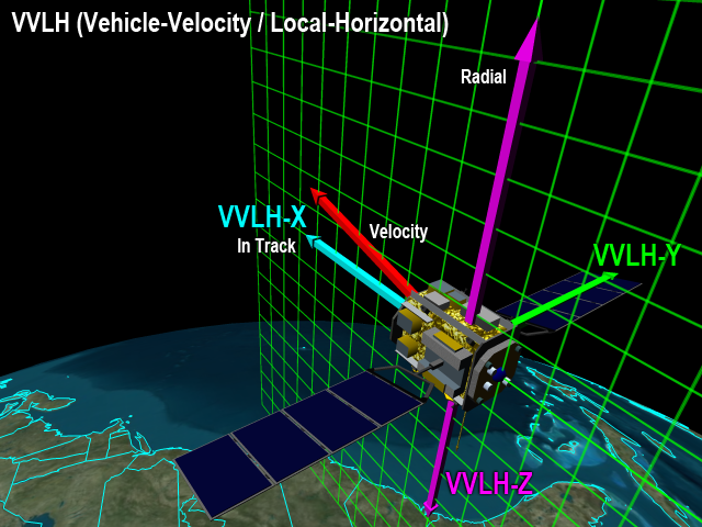
Vehicle Velocity Local Horizontal axes align the Z axis opposite to the position vector and the X axis toward the inertial velocity vector; these are dependent on the object.
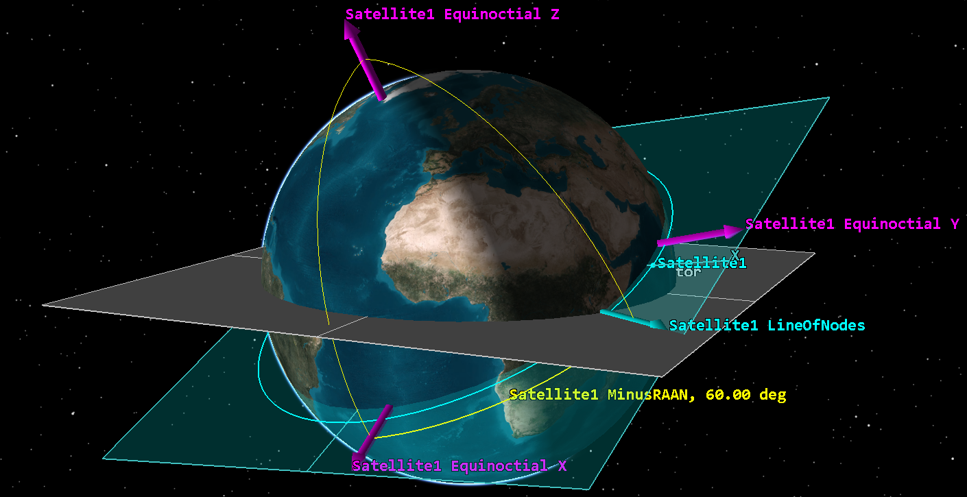
For Equinoctial axes, the Z axis aligns with the orbit normal, and the X axis has a fiducial direction defined by the rotation about the Z axis by the amount -RAAN from the line of nodes. This X axis is sometimes called the fHat direction, with the Y axis called gHat. The X and Y axes lie in the orbit plane but usually evolve slowly and are defined even at 0 degrees inclination. These axes use the posigrade definition and so are undefined at 180 degrees inclination.
Central body surface-based reference frames
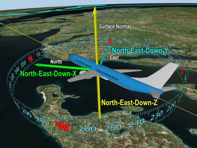
The North East Down axes align the Z axis opposite to the zenith direction with the X axis aligned with the local north direction, and the Y axis is aligned with the local East direction.
The local north and east directions span the tangent plane to the central body surface at the detic subpoint of an object’s position; the zenith direction is perpendicular to the tangent plane (positive outward from the surface).
The detic subpoint is the location on the central body surface having the surface normal direction pass through the object’s position.
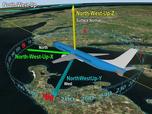
The North West Up axes align the Z axis along the surface normal of the central body reference ellipsoid and the X axis toward the local north direction.
The local north and east directions span the tangent plane to the central body surface at the detic subpoint of an object’s position; the zenith direction is perpendicular to the tangent plane (positive outward from the surface).
The detic subpoint is the location on the central body surface having the surface normal direction pass through the object’s position.
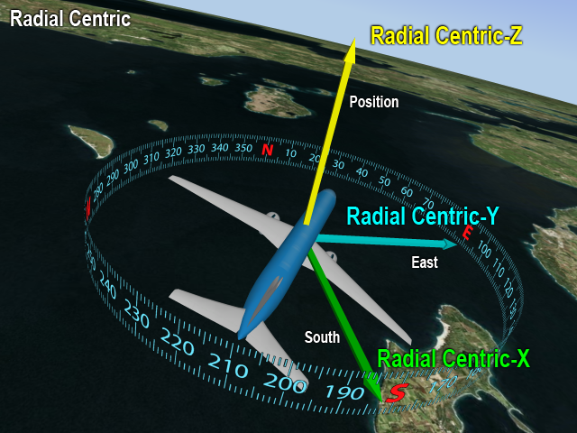
The Radial Centric axes align the Z axis along the position vector and the X axis toward the local south direction.
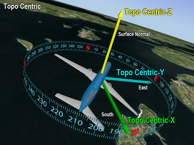
The topocentric axes align the Z axis along the surface normal and the X axis toward the local south direction.
The local north and east directions span the tangent plane to the central body surface at the detic subpoint of an object’s position; the zenith direction is perpendicular to the tangent plane (positive outward from the surface).
The detic subpoint is the location on the central body surface having the surface normal direction pass through the object’s position.
Epoch-based reference frames
The following epoch-based reference frame definitions require you to specify an epoch for creating a specific instance of the reference frame.
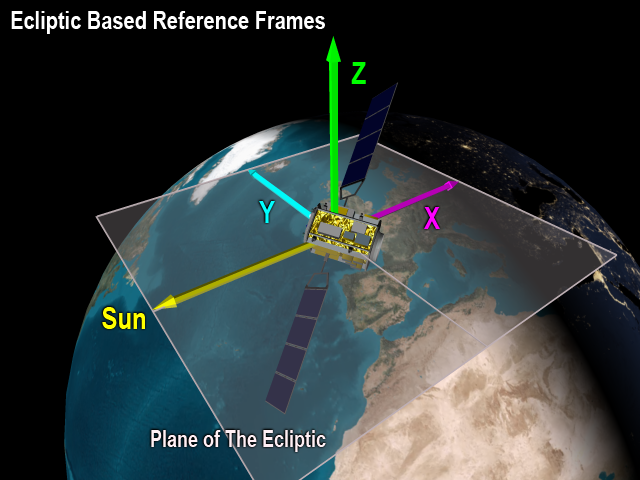
Ecliptic-based reference frames
The VGT provides four ecliptic-based reference frames. All of these reference frames are very similar, and the following image is representative of all of them.
This is the mean ecliptic axes evaluated at the J2000 epoch.
This is the true ecliptic axes evaluated at the J2000 epoch