STK Pro, STK Premium (Air), STK Premium (Space), or STK Enterprise
You can obtain the necessary licenses for this tutorial by contacting AGI Support at support@agi.com or 1-800-924-7244.
The starter scenario used in this tutorial was completed version 12.4 of the STK software. Therefore, this lesson requires version 12.4 of the STK software or newer. However, the Excel workbook steps can be used in version 11.0 of the STK software and newer. You will need to adjust the Connect commands to work with STK objects in your scenarios.
The results of the tutorial may vary depending on the user settings and data enabled (online operations, terrain server, dynamic Earth data, etc.). It is acceptable to have different results.
Capabilities covered
This lesson covers the following capability of the Ansys Systems Tool Kit® (STK®) digital mission engineering software:
- STK Pro
Problem statement
A small unmanned aircraft system (sUAS) drone flies training missions in the vicinity of Mount St. Helens on a continuous basis using the same flight route. The drone sends a television feed back to personnel on the ground. Each day, mission planners change target locations and need to determine if the on-board television camera can see the new targets. If you were one of those mission planners, you would need an quick and simple way to update changes to a small unmanned aircraft system (sUAS) drone.
Solution
You can plan an sUAS drone training mission using the STK software. You can simplify the mission planning process further by creating a new STK scenario from entries in a Microsoft Excel spreadsheet. To update the scenario for your next sUAS mission, you only need to enter new target coordinates.
What you will learn
Upon completion of this tutorial, you will be able to:
- Build Connect commands using the ampersand operator in Excel
- Use the API Demo Utility to transfer Connect commands into the STK application
Video guidance
Watch the following video. Then follow the steps below, which incorporate the systems and missions you work on (sample inputs provided).
Creating a new Excel workbook
First, you need to create an Excel Workbook which you'll use to populate the STK scenario. You can reuse this Excel workbook over and over again whenever mission planners move target locations.
- Open Microsoft Excel.
- Select Blank workbook.
- Select the File menu.
- Select Save As.
- Click Browse.
- Select Desktop in the Save As dialog box.
- Enter TargetGenerator in the File name: field.
- Click .
Naming your columns
Begin by naming the columns in your workbook.
- Find the cells in Row 1.
- Copy and paste the following into your workbook along the first row (you can type them in if you desire):
| Cell | Name |
|---|---|
| A1 | Target ID |
| B1 | Coordinate Type |
| C1 | Latitude |
| D1 | Longitude |
| E1 | New |
| F1 | Set Position |
| G1 | VO Model |
| H1 | Set Height Above Ground |
| I1 | Set Az/El Mask |
| J1 | Set Constraint |
Whenever you place text in a cell that overflows into adjoining cells, you can use your mouse to resize the columns. To use your mouse, rest the cursor on right side of the column boundary you want to move until it becomes a resize cursor (vertical line, horizontal double-headed arrow). Then, you can simply double-click or you can drag the boundary until the column is the width you want.
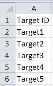
Naming your five Target objects
Your object names cannot contain a space, such as Target 1. You have to name it without a space, such as Target1.
- Double-click on cell A2.
- Type Target1.
- Click cell A2.
- Hover your cursor on the small box in the lower right corner of the cell. Your cursor will turn into a small plus sign.
- Hold down your left mouse button and drag the box to cell A6. This is a quick way to add the remaining targets.
Target ID
Using the Geodetic coordinate type
The STK software provides five ways of positioning the location of the ground for a facility, place, or target. You will use Geodetic Position.
- Double-click on cell B2
- Type Geodetic.
- Click cell B2.
- Hover your cursor on the small box in the lower right corner of the cell B2. Your cursor will turn into a small plus sign.
- Hold down your left mouse button and drag the box to cell B6.
Inserting waypoint coordinates
Mission planners have provided you with the new target coordinates. With every mission, you simply have to update these coordinates and then you can update your STK scenario accordingly. In this scenario, use the coordinates provided.
- Find Columns C and D.
- Type or paste the following latitude (column C) and longitude (column D) coordinates into the workbook:
| Cell | Coordinate |
|---|---|
| C2 | 46.539 |
| C3 | 46.468 |
| C4 | 46.961 |
| C5 | 46.568 |
| C6 | 46.2 |
| D2 | -122.97 |
| D3 | -122.613 |
| D4 | -122.313 |
| D5 | -122.027 |
| D6 | -122.186 |
Understanding Connect
The Connect module provides you with an easy way to connect with STK and work in a client-server environment. You can use the library shipped with Connect to easily build applications that communicate with the STK software. This library contains functions, constants and other messaging capabilities that you can use to connect third-party applications to the STK application. With Connect, you can generate optional diagnostic messages. Additionally, Connect allows you to override the standard messaging and modify it or you can use your own messaging format for compatibility with third-party applications. These features allow you to better control the messaging environment.
Connect communicates with the STK application and 3D Graphics so you can visualize events in real-time. For instance, you can use Connect to feed real-time telemetry data from the launch and early orbit of a mission. As a scenario, the data can be viewed in 2D or 3D to visualize the mission and assist in understanding and resolving any issues that may arise.
Although not required for this lesson, you may want to familiarize yourself with these selected Connect Help files if you plan to continue working with Connect commands. These pages provide the basics for anyone starting with Connect:
- Getting Started with Connect
- Example Connect Command
- Connect Command Syntax Elements Command Syntax Elements
Take some time to view all the Help files associated with Integrating with STK. The above Help files will help you to understand the Connect commands you are building and sending to this scenario.
Using the Concatenate operator in Excel
You can easily build Connect commands using the Concatenate operator (&) in Excel. It is used to force string concatenation of two expressions. An expression is a combination of keywords, operators, variables, and constants that yields a string, number, or object. You can use an expression to perform a calculation, manipulate characters, or test data.
Creating the New Connect command in a way Excel understands
You can use the New Connect Command to create a new STK scenario or add a new STK object to the current scenario. In Excel, you have to create a line of text (or a string) that contains the New Command. When you run your Excel workbook into the STK application, the STK software will execute the Connect commands written in your Excel workbook. In this case, you are writing five New Commands in Excel so STK will add five Target objects to your STK scenario.
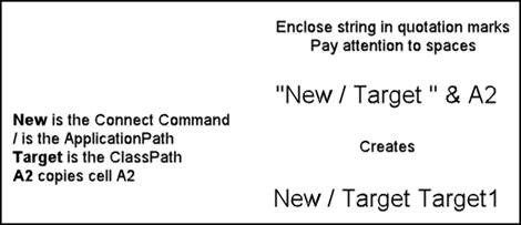
In the STK software, the New Connect Command has this syntax: New <ApplicationPath> <ClassPath> <NewObjectName> {NewOptions}. You need to replicate that syntax in a way that Excel can understand before Excel can pass this command to the STK software.
- Bring your Excel workbook to the front.
- Type the equals sign " = " into cell E2.
- Copy and paste (or type) the following text string into cell E2 after the equals sign (make sure to accurately write the quotation marks, spaces, and the ampersands):
- Press the Enter key on your keyboard. Check your equals sign, spacing, and ampersands if you receive an error.
- Expand the width of column E to read the connect command.
- Ensure that "New / Target Target1" has appeared in cell E2.
"New / Target " & A2
If you've entered it correctly, the formula bar should look like this:
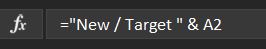
Formula Bar
Essentially, you told Excel that cell E2 should contain (or "equals") the line of text "New / Target " and whatever is in cell A2. Now, whenever you update the TargetID in cell A2, your New Command in cell E2 will update automatically. However, the STK software will just see cell E2 as New / Target Target1 rather than a complicated formula of equals signs and quotes. You will repeat this thought process for all the Connect commands in the excel sheet.
Ampersand operator
Duplicating the command down column E
You have created one Target object for Target1. You can save time by replicating the command for Target2 through Target5.
- Click cell E2.
- Locate the small black box on the lower right corner of the cell.
- Place your cursor on the box and it will turn into a small plus sign.
- Hold down your left mouse button and drag the box to cell E6. Four New commands should appear in cells E3 through E6.
Creating the SetPosition command in Excel
In the STK software, you use the SetPosition Command to set the position of a facility, place, target or area target. To create a SetPosition Command, you can use the same process you used with the New Connect command. The SetPosition command will move the Target objects to the specified Geodetic coordinates in the STK application and place the Targets on top of the terrain at that coordinate.
In the STK software, the SetPosition Connect Command has this syntax: SetPosition <ObjectPath> [{Type}] {CoordType} <Parameters>. You need to replicate that syntax in a way that Excel can understand before Excel can pass this command to the STK application.
- Type the equals sign " = " into cell F2.
- Copy and paste (or type) the following text string into cell F2 after the equals sign (make sure to accurately write the quotation marks, spaces, and the ampersands):
- Press the Enter key on your keyboard. Check your equals sign, spacing, and ampersands if you receive an error.
- Expand the width of column F to read the Connect command.
- Ensure that "SetPosition */Target/Target1 Geodectic 46.539 -122.97 Terrain" has appeared in cell F2.
- Click cell F2.
- Locate the small black box on the lower right corner of the cell.
- Place your cursor on the box and your cursor will turn into a small plus sign.
- Hold down your left mouse button and drag the box to cell F6. You should have SetPosition commands for all five of the Target objects.
"SetPosition */Target/" & A2 & " " & B2 & " " & C2 & " " & D2 & " Terrain"Creating the VO Model command in Excel
Use the VO Model Connect Command to assign a model to a facility, place, target or vehicle (any type). The Target objects currently have their models turned off in the 3D Graphics window. Use the VO Model command to turn the model on visually in your scenario.
In the STK software, the VO Model Connect Command has this syntax VO <ObjectPath> Model {Option1} <Value1> [{Option2} <Value2>]... and you need to replicate that in Excel for the STK software to understand your Excel workbook.
- Type the equals sign " = " into cell G2.
- Copy and paste (or type) the following text string into cell G2 after the equals sign (make sure to accurately write the quotation marks, spaces, and the ampersands):
- Press the Enter key on your keyboard. Check your equals sign, spacing, and ampersands if you receive an error.
- Expand the width of column G to read the Connect command.
- Ensure that "VO */Target/Target1 Model Show On" has appeared in cell G2.
- Click cell G2.
- Locate the small black box on the lower right corner of the cell.
- Place your cursor on the box and your cursor will turn into a small plus sign.
- Hold down your left mouse button and drag the box to cell G6. You should have VO Model commands for all five of the Target objects.
"VO */Target/" & A2 & " Model Show On"Creating the SetHeightAboveGround command in Excel
Use the SetHeightAboveGround command to set the height above ground of a facility, place or target. The Target objects' center points are located on the surface of the terrain. Use the SetHeightAboveGround command to add additional height to your Target objects to simulate the actual height of an attached transmitter, receiver, sensor, radar, etc.
In the STK software, the SetHeightAboveGround Connect Command has this syntax SetHeightAboveGround <ObjectPath> <Height> and you need to replicate that in Excel for the STK software to understand your Excel workbook.
The default units Connect distance unit is meters.
- Type the equals sign " = " into cell H2.
- Copy and paste (or type) the following text string into cell H2 after the equals sign (make sure to accurately write the quotation marks, spaces, and the ampersands):
- Press the Enter key on your keyboard. Check your equals sign, spacing, and ampersands if you receive an error.
- Expand the width of column H to read the Connect command.
- Ensure that "SetHeightAboveGround <ObjectPath> <Height>" has appeared in cell H2.
- Click cell H2.
- Locate the small black box on the lower right corner of the cell.
- Place your cursor on the box and your cursor will turn into a small plus sign.
- Hold down your left mouse button and drag the box to cell H6. You should have SetHeightAboveGround commands for all five of the Target objects.
"SetHeightAboveGround */Target/" & A2 & " 3"Creating the SetAzElMask (Facility, Place & Target) command in Excel
Use the SetAzElMask (Facility, Place & Target) command to set the azimuth-elevation mask for a facility, place or target. You need to take terrain into consideration when using the television camera. Use the SetAzElMask command to create 360 degree AzEl Masks which will use the analytical terrain.
In the STK software, the SetAzElMask Command has this syntax: SetAzElMask <ObjectPath> {UseOption} ["<FilePath>"]
- Type the equals sign " = " into cell I2.
- Copy and paste (or type) the following text string into cell I2 after the equals sign (make sure to accurately write the quotation marks, spaces, and the ampersands):
- Press the Enter key on your keyboard. Check your equals sign, spacing, and ampersands if you receive an error.
- Expand the width of column I to read the Connect command.
- Ensure that "SetAzElMask */Target/Target1 Terrain" has appeared in cell I2.
- Click cell I2.
- Locate the small black box on the lower right corner of the cell.
- Place your cursor on the box and your cursor will turn into a small plus sign.
- Hold down your left mouse button and drag the box to cell I6. You should have SetAzElMask commands for all five of the Target objects.
"SetAzElMask */Target/" & A2 & " Terrain"Creating the SetConstraint (Facility, Place & Target) command in Excel
Use the SetConstraint (Facility, Place & Target) command to set a constraint for a facility, place, or target object. Use the SetConstraint (Facility, Place & Target) command to enable the AzEl Masks to be used during an access.
In the STK software, the SetConstraint Command has this syntax: SetConstraint <ObjectPath> {ConstraintName} <Parameters>
- Type the equals sign " = " into cell J2.
- Copy and paste (or type) the following text string into cell J2 after the equals sign (make sure to accurately write the quotation marks, spaces, and the ampersands):
- Press the Enter key on your keyboard. Check your equals sign, spacing, and ampersands if you receive an error.
- Expand the width of column J to read the Connect command.
- Ensure that "SetConstraint */Target/Target1 AzElMask On" has appeared in cell J2.
- Click cell J2.
- Locate the small black box on the lower right corner of the cell.
- Place your cursor on the box and your cursor will turn into a small plus sign.
- Hold down your left mouse button and drag the box to cell J6. You should have SetAzElMask commands for all five of the Target objects.
"SetConstraint */Target/" & A2 & " AzElMask On"Importing a starter scenario
A partially created scenario has been created for you to focus on transferring your Connect commands into the STK application.
- Launch the STK application (
 ).
). - Ensure that the Welcome to STK dialog box is visible in the STK Workspace.
- Click Open a Scenario.
- Browse to <Install Dir>\Data\Resources\stktraining\VDFs (e.g. C:\Program Files\AGI\STK_ODTK 13\Data\Resources\stktraining\VDFs).
- Select Connect_Starter.vdf.
- Click .
Saving a VDF as a scenario file
When you open the scenario, the STK software creates a directory with the same name as the scenario in the default user directory (e.g. C:\Users\<username>\Documents\STK_ODTK 13). The scenario will not save automatically. When you save a scenario in the STK application, the file will not change its file type automatically. In other words, if you open a Visual Data File (VDF), the default save format will still be a VDF. The same is true for a scenario file (*.sc). If you want to save a VDF as an SC file (or vice-versa), you must change the file format when you are performing the Save As procedure.
- Open the File menu after your scenario loads.
- Select Save As...
- Select the STK User (
 ) folder in the Navigation pane.
 - Double-click the Connect_Starter () folder.
- Select Scenario Files (*.sc) from the Save as type: drop down's options.
- Click .
- Click to confirm.
Save often!
Understanding the starter scenario
Prior to modifying the scenario, you should become familiar with the objects already created in the starter scenario.
- Open the Window menu.
- Select Tile Vertically.
- Look at the scenario modeled in the 2D and 3D Graphics windows.
The sUAS drone is flying a search pattern in the vicinity of Mount St. Helens and is using a simple conic Sensor object to simulate the field of view of the on-board television camera. You are using a local terrain file (StHelens_Training.pdtt) both analytically and visually which you can see in the Globe Manager.
Using the Web Browser transfer the Connect commands to STK
The Web Browser works like most traditional web browsers except that it is an integrated part of the STK workspace. You can set the Web Browser to display any HTML document at startup. You can use the Web Browser to open the API Demo Utility, which runs Connect Commands.
- Bring the STK application to the front.
- Open the View menu.
- Select Web Browser.
- Click Browse (
 ) in the Web Browser toolbar.
Using the API Demo Utility
The API Demo Utility will allow you to send Connect commands into the current scenario. This is a great tool to use if you're creating Connect commands or practicing with Connect.
Sample HTML Utilities are included with the STK application and available for download from the AGI website. They are available for common analysis, parallel processing, creating and manipulating objects, importing data, STK automation, and view control. There are many ways to transfer Connect commands into the STK application. For your purposes in this lesson, you can just focus on the API Demo Utility.
- Select in the Open dialog box.
- Select STK Automation ().
- Click .
- Select API Demo ().
- Click .
- Select API Demo Utility.htm.
- Click .
Running the New commands
Copy your Connect commands in the Excel workbook and paste them into the API Demo Utility starting with the New and SetPosition Connect commands. You will then use the API Demo Utility to send Connect commands into your scenario.
- Return to the Excel workbook.
- Select cells E2 through E6.
- Copy the cells by clicking Ctrl + C on your keyboard.
- Return to the STK application.
- Remove all text from the API Demo Utility Code Sandbox.
- Paste the New Connect commands into the Code Sandbox.
Running the SetPosition commands
- Return to the Excel workbook.
- Copy the cells F2 through F6.
- Return to the STK application.
- Paste the SetPosition commands into the Code Sandbox beneath the New commands. You have to generate the targets prior to setting their locations.
- Click .
![]()
Code Sandbox
Viewing your scenario changes
Look at the STK application and its objects to see if your Connect commands worked properly.
- Look at the Object Browser. You should see five (5) new Target (
 ) objects in your scenario.
 - Open Target1's () properties (
 ).
). - Select the Basic - Position page. If you compare the latitude and longitude values you copied from your Excel workbook, you can see they are correct. Also, you enabled Use terrain data.
- Keep Target1's () properties () open.
Running the VO and SetHeightAboveGround commands
Copy and paste the VO Model and SetHeightAboveGround commands from the Excel workbook to the API Demo Utility. Before you do that, look at the properties that the Connect commands will change.
- On the Basic - Position page, notice that Height Above Ground is set at 0 km.
- Select the 3D Graphics - Model page.
- Notice Show is turned off in the Model panel.
- Click to close Target1's () properties ().
- Remove the Connect commands from the Code Sandbox.
- Return to the Excel workbook.
- Copy all of the VO Model Connect commands.
- Return to the STK application.
- Paste all five VO Model Connect commands into the API Demo Utility Sand Box.
- Return to the Excel workbook.
- Copy all five SetHeightAboveGround commands.
- Paste the SetHeightAboveGround commands into the API Demo Utility below the VO commands.
- Click .
Viewing your scenario changes
- Open Target1's () properties ().
- Select the Basic - Position page. You can see that Height Above Ground: is now set at 0.003 km (3 meters).
- Select the 3D Graphics - Model page. You can see that Show is now turned on in the Model File: field.
- Close Target1's () properties ().
- Remove the Connect commands from the Code Sandbox.
- Return to the Excel workbook.
Running the SetAzElMask and SetConstraint Connect commands
Copy and paste the SetAzElMask and SetConstraint commands to the API Demo Utility.
- Copy all five SetAzElMask commands.
- Paste all five SetAzElMask commands to the API Demo Utility.
- Copy all five SetConstraint commands.
- Paste all five SetConstraint commands to the API Demo Utility below the SetAzElMask commands. You have to create the AzElMask files prior to turning them on for accesses.
- Click .
Viewing your scenario changes
- Open Target1's () properties ().
- Select the Basic - AzElMask page. You can see that Use: Terrain Data is set and Use Mask for Access Constraint is turned on.
- Close Target1's () properties ().
- Remove the Connect commands from the Code Sandbox.
On your own: building Connect commands in Excel
After practicing with six different Connect commands, you have the tools to add any Connect Command to the lesson using your Excel workbook and the STK Help. For instance, let's test you skills! Try building an STK Connect command that will create an access between the TV_FOV Sensor object and all five Target objects. If done correctly, you will see the individual accesses in the API Demo Utility's Output field. Here's some steps to help you start:
- Open the Help menu in STK.
- Select STK Help.
- Select Integrating with STK on the left when the STK Help opens.
- Select Connect Command Library.
- Select Alphabetical Listing.
- Locate the Access Connect command on the list. Note the syntax and examples the help provides.
- Return to your Excel workbook.
- Type Access in cell L1 to create a new Access heading The direction that the aircraft is pointing..
- Create a Connect command that creates an access from TV_FOV (
 ) to all five Target () objects using cells L2 through L6. Use your experience with previous Connect commands in this lesson and the STK Help as a guide.
 - Copy the Access commands from the Excel workbook to the STK application.
- Click .
Done correctly, you will see the individual accesses in the Output field.
Summary
You created an Excel workbook which can be saved and used each time you mission plan an sUAS mission. Although you had five targets in this scenario, you could have less or more, depending on mission planning and priorities. For complex mission with many moving parts, an Excel workbook helps you keep track of all the objects and replicate objects quickly.
In this lesson, your focus was placing the targets at their updated coordinates, placing them on top of analytical terrain, raising them an additional 3 meters above the ground, creating azimuth / elevation masks and using the masks as an access constraint. You also manipulated the 3D graphics model of each target. You opened a prebuilt STK scenario and loaded the new targets into the scenario by transferring the Connect commands from the Excel workbook to the STK scenario via the API Demo Utility.
On your own
Hyperlinks were used throughout the tutorial. Now is a good time to go back through the tutorial and take time to view those links. Create your own scenario and build Connect commands to manipulate objects in the scenario.