STK Premium (Space) or STK Enterprise
You can obtain the necessary licenses for this tutorial by contacting AGI Support at support@agi.com or 1-800-924-7244.
This lessons uses the Visual Basic Scripting Edition (VBScript) scripting language. Microsoft has announced that VBScript is deprecated and will be removed from future versions of Windows. You can continue to use VBScript with the STK software in current versions of Windows. Refer to Microsoft's documentation for more information and the deprecation timeline.
The results of the tutorial may vary depending on the user settings and data enabled (online operations, terrain server, dynamic Earth data, etc.). It is acceptable to have different results.
This lesson requires version 13.0 of the STK software or newer to complete in its entirety. If you have an earlier version of the STK software, you can complete a legacy version of this lesson.
Capabilities covered
This lesson covers the following capabilities and tools of the Ansys Systems Tool Kit® (STK®) digital mission engineering software:
- STK Pro
- Astrogator
- Analysis Workbench
Problem statement
When designing a maneuver that requires a large Delta-V, engineers and operators need to model a finite maneuver to properly simulate a satellite’s trajectory, especially when they have a low-thrust engine on the satellite. They need to take into account the available power from the solar panels to constrain the engine's possible thrust, which requires the definition of a main propagation flow during which the satellite does not maneuver, and configure an on-board automatic sequence to initiate a burn when a minimum amount of power is available.
Solution
Use the STK/Astrogator® and Analysis Workbench capabilities to design an orbit-raising strategy to move the satellite from a low Earth orbit (LEO) to a medium Earth orbit (MEO). Use a low-thrust engine and a nested Automatic Sequence, which contains a Maneuver segment and a custom plugin script, to fire the engine when a constraint is satisfied. You must account for different Sun-related constraints during the engine burn. You will analyze each of these constraints using the using three Satellite objects in the following order:
- A satellite in direct sunlight
- A satellite with a positive Sun incidence angle over the solar panels
- A satellite requiring a minimum power output from its solar panels
What you will learn
Upon completion of this tutorial, you will be able to:
- Create an Astrogator Automatic Sequence
- Use the Analysis Workbench capability to create custom components
- Create a custom Plugin Script for the Vector Geometry Tool
- Use a User Calculation Object with the Astrogator capability
Creating a new scenario
First, you must create a new STK scenario, and then build from there.
- Launch the STK application (
 ).
). - Click
 Create a Scenario when the Welcome to STK dialog box opens.
 - Enter the following in the STK: New Scenario Wizard:
- Click when you finish.
- Click Save (
 ) when the scenario loads. The STK application creates a folder with the same name as your scenario for you.
 - Verify the scenario name and location in the Save As dialog box.
- Click .
| Option | Value |
|---|---|
| Name | FiniteThrustWithSun |
| Start | 25 Jan 2025 00:00:00.000 UTCG |
| Stop | 10 Feb 2025 00:00:00.000 UTCG |
Save (![]() ) often during this scenario!
) often during this scenario!
Preparing your workspace
Close the 2D Graphics window and the Timeline View They are not needed for this exercise.
- Click Close (
 ) to close the 2D Graphics window.
 - Click Close () to close the Timeline View.
- Click Maximize (
 ) in the 3D Graphics window to fill the integrated workspace with the 3D Graphics window.
Creating a custom low-thrust engine model
Using the Component Browser, you can customize a low-thrust engine model for the Satellite objects in your scenario. An engine model component models the thrust and specific impulse (Isp) of a rocket engine.
Opening the Component Browser
The
- Select the Utilities menu.
- Select Component Browser... (
 ).
).
Creating a new engine model component
Duplicate the
- Select the Engine Models (
 ) folder in the View All Components list.
 - Select Constant Thrust and Isp (
 ) in the Engine Models list.
 - Click Duplicate component (
 ) in the Engine Models toolbar.
 - Enter Low Thrust in the Name field when the Field Editor dialog box opens.
- Click to accept your change and to close the Field Editor dialog box.
Configuring the custom Low Thrust engine model
Edit the duplicated component's properties to model the thrust and Isp of your low-thrust engine.
- Select Low Thrust (
 ) in the Engine Model list.
 - Click View properties (
 ) in the Engine Models toolbar.
 - Double-click on Thrust when the Low Thrust dialog box opens.
- Enter 0.1 N in the Real Number field when the Real Number Field dialog box opens.
- Click to accept your change and to close the Real Number Field dialog box.
- Double-click on Isp.
- Enter 1900 s in the Real Number field.
- Click to accept your change.
Adding a component to your collection
You can save a custom-built component to your User Collection and make it available in other scenarios.
- Click in the Low Thrust dialog box.
- Click to close the Component Browser.
Note that the icon for Low Thrust (![]() ) has been updated to indicate it is now a part of your User Collection.
) has been updated to indicate it is now a part of your User Collection.
You will use this Low Thrust engine model for all of your Satellite objects during this scenario.
Modeling a satellite in sunlight
Insert the first of three Satellite objects into the scenario. This first Satellite object will model a satellite whose maneuvering is only constrained by when its body is in sunlight.
Inserting a new Satellite object
Use the Insert STK Objects tool to add a Satellite object to your scenario.
- Bring the Insert STK Objects tool (
 ) to the front.
 - Select Satellite (
 ) in the Select An Object To Be Inserted list.
 - Select Insert Default () in the Select A Method list.
- Click .
- Right-click on Satellite1 () in the Object Browser.
- Select Rename in the shortcut menu.
- Rename Satellite1 () BodyInSunlight.
Setting the propagator to Astrogator
The Astrogator capability contains specialized analysis for interactive orbit maneuver and spacecraft trajectory design. Astrogator processing calculates the satellite's ephemeris by running a Mission Control Sequence, or MCS, that you define according to the requirements of your mission.
- Right-click on BodyInSunlight () in the Object Browser.
- Select Properties () in the shortcut menu.
- Select the Basic - Orbit page when the Properties Browser opens.
- Open the Propagator drop-down list.
- Select Astrogator.
Setting the Initial State's segment properties
Use the
- Select the Initial State (
 ) segment in the MCS.
 - Select the Elements tab.
- Open the Coordinate Type drop-down list.
- Select Keplerian.
- Set the following orbital element values:
- Leave the rest of the orbital elements at their default values.
- Click to accept your changes and to keep the Properties Browser open.
| Option | Value |
|---|---|
| Semi-major Axis | 7000 km |
| Eccentricity | 0 |
Adding an R Magnitude stopping condition
Use the
- Select the Propagate (
 ) segment in the MCS.
 - Click New... (
 ) in the Stopping Conditions panel toolbar.
 - Select R Magnitude () in the New Stopping Condition dialog box.
- Click to accept your selection and to close the New Stopping Condition dialog box.
- Set the following R Magnitude properties:
- Click to accept your changes and to keep the Properties Browser open.
| Option | Value |
|---|---|
| Trip | 20000 km |
| Tolerance | 1 km |
These parameters represent the overall final condition for propagation. The next stopping condition you will add will be triggered multiple times and initiate Automatic Sequences rather than stop the propagation.
Adding a Lighting stopping condition
The low-thrust engine is used only when the satellite is in sunlight. Add a Lighting stopping condition that is satisfied when the spacecraft enters direct sunlight. This way, you can trigger an Automatic Sequence containing a finite maneuver, which you will create, that will initiate when the satellite enters direct sunlight.
- Click New... () in the Stopping Conditions panel toolbar.
- Select Lighting () in the New Stopping Condition dialog box.
- Click to accept your selection and to close the New Stopping Condition dialog box.
- Double-click on Lighting in the Name column.
- Enter Coasting as the new name.
- Open the Condition drop-down list.
- Select Enter Direct Sun.
- Select Duration in the Stopping Conditions panel list.
- Click Delete (
 ) in the Stopping Conditions panel toolbar.
Setting Earth Point Mass as the propagator
The Astrogator capability will apply the propagator named in the Propagator text field. Use Earth Point Mass as the propagator. This will reduce the computational time, while still providing useful results.
- Click the Propagator ellipsis (
 ).
). - Select Earth Point Mass () in the Select Component dialog box.
- Click to accept your selection and to close the Select Component dialog box.
- Click .
Creating an Automatic Sequence
The Astrogator capability enables you to define
- Click Automatic Sequence Browser (
 ) in the MCS toolbar.
 - Click in the Automatic Sequence Browser dialog box.
- Enter Sunlight Maneuver in the Name field of the Field Editor dialog box.
- Click to accept your change and to close the Field Editor dialog box.
Editing the Automatic Sequence
Edit the contents of your Automatic Sequence.
- Select Sunlight Maneuver in the Automatic Sequence Browser dialog box.
- Click to open the Automatic Sequence Properties dialog box.
Updating the Automatic Sequence properties
The Automatic Sequence Properties dialog box is a scaled-down version of the MCS. It provides the same toolbar buttons for inserting, removing, and editing MCS segments that are found on the MCS toolbar.
- Click Insert Segment After () in the Automatic Sequence Properties dialog box toolbar.
- Select Maneuver (
 ) in the Segment Selection dialog box.
 - Click to accept your selection and to close the Segment Selection dialog box.
Updating the Maneuver segment properties
Rename the Maneuver segment and change its color. A finite maneuver can be visualized in the 3D Graphics window.
- Select Maneuver () in the Automatic Sequence Properties dialog box list.
- Click Segment Properties () in the Automatic Sequence Properties dialog box toolbar.
- Enter Sun Constrained in the Name field of the Edit Segment dialog box.
- Open the Color drop-down list.
- Select Red.
- Click to accept your changes and to close the Edit Segment dialog box.
Using a Finite Maneuver
A
- Open the Maneuver Type drop-down list.
- Select Finite.
Setting the propagator
Set the propagator to Earth Point Mass.
- Click the ellipsis () next to the Finite Propagator and Force Model for Optimization field.
- Select Earth Point Mass () in the Select Component dialog box.
- Click to accept your selection and to close the Select Component dialog box.
Setting the Attitude control
The thrust vector describes the direction of acceleration applied to a satellite. You can specify how the maneuver pointing and the spacecraft's attitude are updated. In this instance, your satellite is thrusting in one direction.
- Select the Attitude tab.
- Note the default Attitude Control setting of Along Velocity Vector.
- Note the default Attitude Update setting of Update during burn.
The satellite object’s attitude is defined as the Delta-V vector aligned with or opposite to the spacecraft's inertial velocity vector. The inertial reference frame depends on the central body of the satellite object.
The attitude is updated throughout the maneuver so as to maintain the required thrust direction. This forces the thrust vector to the specified direction at every instant throughout the burn.
Selecting the Low Thrust engine model
Use your custom low-thrust engine model.
- Select the Engine tab.
- Click the Engine Model ellipsis () in the Propulsion Type panel.
- Select Low Thrust (
 ) in the Select Component dialog box.
 - Click to accept your selection and to close the Select Component dialog box.
Adding a stopping condition
Add a lighting stopping condition so that the maneuver will stop when the satellite exits direct sun.
- Select the Propagator tab.
- Click New... () in the Stopping Conditions panel toolbar.
- Select Lighting () in the New Stopping Condition dialog box.
- Click to accept your selection and to close the New Stopping Condition dialog box.
- Note that the Condition is set to Exit Direct Sun by default.
- Select the Duration stopping condition.
- Click Delete () in the Stopping Conditions panel toolbar.
- Click to accept your changes and to close the Automatic Sequence Properties dialog box.
- Click to close the Automatic Sequence Browser dialog box.
- Click to accept your changes and to keep the Properties Browser open.
Modifying the graphics for situational awareness
Modify the graphics settings so that you can view the satellite's entire orbit. Specifically, you want to see when a portion of the orbit is in umbra or direct Sun.
- Select the to the 3D Graphics - Pass page.
- Open the Lead Type drop-down list in the Orbit Track panel.
- Select All.
- Select the 2D Graphics - Lighting page.
- Select the Umbra check box.
- Click to accept your changes and to keep the Properties Browser open.
Implementing the Automatic Sequence
You created an Automatic Sequence that will apply a thrust force, using the custom engine you previously defined, only when the satellite is in direct sunlight. You can update the Propagate segment to trigger the Automatic Sequence when the Coasting stopping condition is satisfied.
- Select the Basic - Orbit page.
- Select Coasting in the Stopping Conditions panel.
- Click the Sequence ellipsis ().
- Select Sunlight Maneuver () in the Select Component dialog box.
- Click to accept your selection and to close the Select Component dialog box.
- Click to accept your changes and to keep the Properties Browser open.
Running the entire Mission Control Sequence
To calculate the trajectory of the spacecraft, you must run the Mission Control Sequence. Astrogator will proceed through the MCS and run each segment, generating an ephemeris for the spacecraft. As it runs the MCS, Astrogator carries the trajectory and state of the spacecraft determined so far from one segment to the next.
- Click Run Entire Mission Control Sequence (
 ) in the MCS toolbar.
 - Click Clear Graphics (
 ).
). - Click to accept your changes and to close the Properties Browser.
Viewing BodyInSunlight's orbit in the 3D Graphics window
Look at the orbit in the 3D Graphics window.
- Bring the 3D Graphics window to the front.
- Click Home View (
 ) in the 3D Graphics window toolbar.
 - Use your mouse buttons to zoom out and rotate the view so get an idea of the colors marking the orbit.
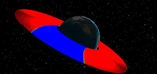
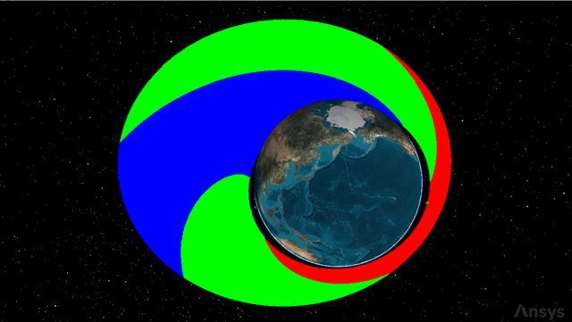
BodyInSunlight's orbit
The red portion of the orbit is when the satellite executes its low-thrust maneuver while in direct sun. The green stripes are penumbra and the blue portion is when the satellite is in umbra.
Creating a Maneuver Summary report
Now that you have modeled the satellite's orbit and visualized its behavior, examine the results in a Maneuver Summary report to get an overview about the engine's performance.
- Right-click on BodyInSunlight () in the Object Browser.
- Select Report & Graph Manager... (
 ) in the shortcut menu.
 - Select the Maneuver Summary (
 ) report in the Installed Styles () folder in the Styles panel.
 - Click .
- Scroll through the Maneuver Summary report.
- Close the report when finished viewing the data.
The maneuver durations increase as the satellite spirals outward and the time spent in sunlight increases along with the period.
Creating a custom graph
Create a custom graph showing BodyInSunlight's semi-major axis over time.
Creating a new graph
Create a new graph style for your custom graph.
- Select My Styles () in the Styles panel list.
- Click Create new graph style (
 ) in the Styles toolbar.
 - Enter Semimajor Axis while in rename mode.
- Select the Enter key to accept your change and to open the report's properties.
Selecting data providers, groups, and elements
When the graph's properties open, you will see the data providers list on the left side of the Properties Browser and the graph contents list on the right side. The content of a report or graph is generated from the selected data providers for the report or graph style.
- Select the Content page in the Properties Browser.
- Expand (
 ) the Classical Elements () data provider in the data provider list.
 - Expand () the ICRF () data provider group.
- Select the Semi-major Axis (
 ) data provider element.
 - Click Insert Y Axis (
 ) in the Y Axis panel.
 - Click to accept your selection and to close the Properties Browser.
Generating the custom graph
With your data provider selected, generate the graph.
- Select the Semimajor Axis (
 ) graph in the My Styles () folder in the Styles panel.
 - Click .
- Close the graph and the Report & Graph Manager when finished.
- Clear the BodyInSunlight () check box in the Object Browser.
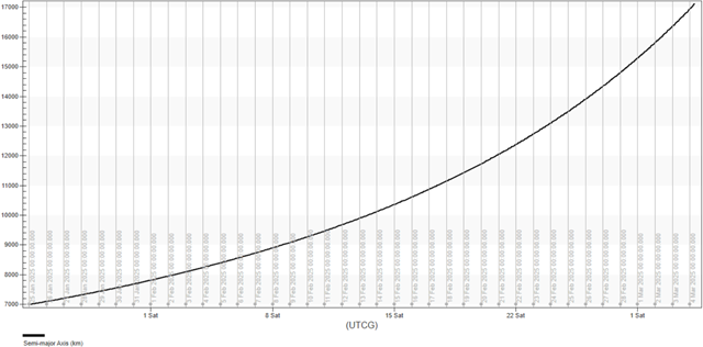
Semimajor axis graph
The graph shows the increase in the satellite's semi-major axis during the analysis period of your scenario.
This removes the visuals from the 2D and 3D Graphics windows, but BodyInSunlight is still available analytically.
You simulated a satellite's orbit raising while leveraging when the satellite appears in direct sunlight as a simple control law. Next, you will increase the realism of your analysis.
Modeling a satellite with fixed solar panels
Unlike the previous analysis where you applied a simple sunlight constraint to the satellite, now you will constrain a satellite's maneuvering to when the Sun vector has a positive incidence angle over the solar panels. The solar panels are fixed with respect to the satellite's body in this case. By building on your first analysis, the following steps will increase the fidelity of your scenario.
Inserting a second Satellite object
Add another Satellite object to your scenario.
- Insert a Satellite () object using the Insert Default () method.
- Rename Satellite2 () FixedSolarPanels.
Setting the propagator to Astrogator
Set the satellite's propagator to use Astrogator.
- Open the FixedSolarPanels' () Properties ().
- Select the Basic - Orbit page.
- Open the Propagator drop-down list.
- Select Astrogator.
Modifying the graphics for situational awareness
Modify the graphics settings so that you can view the satellite's entire orbit. Specifically, you want to see when a portion of the orbit is in umbra or direct Sun.
- Select the to the 3D Graphics - Pass page.
- Open the Lead Type drop-down list in the Orbit Track panel
- Select All.
- Select the 2D Graphics - Lighting page.
- Select the Umbra check box.
- Click to accept your changes and to keep the Properties Browser open.
Defining the initial state
Set the orbital properties for the satellite.
- Select the Basic - Orbit page.
- Select the Initial State () segment in the MCS.
- Select the Elements tab.
- Open the Coordinate Type drop-down list.
- Select Keplerian.
- Set the following orbital element values:
- Leave the rest of the orbital elements at their default values.
- Click to accept your changes and to keep the Properties Browser open.
| Option | Value |
|---|---|
| Semi-major Axis | 7000 km |
| Eccentricity | 0 |
Propagating the satellite and viewing the model articulations
The articulated solar panels in the 3D model of the Satellite object point towards the Sun by default.
- Click Run Entire Mission Control Sequence () in the MCS toolbar.
- Click Clear Graphics () in the MCS toolbar.
- Click to accept your changes and to keep the Properties Browser open.
- Bring the 3D Graphics window to the front.
- Right-click on FixedSolarPanels () in the Object Browser.
- Select Zoom To in the shortcut menu.
- Click Start (
 ) in the Animation toolbar to animate your scenario.
 - Click Reset (
 ) in the Animation toolbar when finished.
You can see the solar panels are articulated to follow the Sun.
Locking the solar panels to a fixed orientation
While you can point the solar panels towards an available target, you can also direct them to remain stationary. In this case, make them fixed with respect to the spacecraft body by updating the Satellite object's
- Return to FixedSolarPanels () Properties ().
- Select the 3D Graphics - Model Pointing page.
- Select None in the Available Targets panel.
- Click to accept your changes and to keep the Properties Browser open.
Setting an Articulation - Transformation value
You can view, establish, or modify the articulated (movable) parts of a 3D model that contains articulations and transformations by updating its
- Select the 3D Graphics - Model page.
- Click in the Articulations panel.
- Select SolarPanels in the Articulations panel in the Model Articulations dialog box.
- Look in the Transformations panel. The transformation is Rotate.
- Use the slider to modify the transformation value to the right of the Transformations panel or by entering a value to set the Transformation to 0.0000.
- Click to accept your change and to close the Model Articulations dialog box.
- Click to accept your changes and to keep the Properties Browser open.
Viewing the fixed orientation solar panels
The solar panels should now have a fixed orientation respect to the satellite body. Also, they should align with the local horizontal plane.
- Bring the 3D Graphics window to the front.
- Click Start () in the Animation toolbar to animate your scenario.
- Click Reset () in the Animation toolbar when finished.
You can see the solar panels are now fixed (not rotating) and align with the satellite model's local horizontal plane.
Using the Vector Geometry tool
Create a new angle component using the Analysis Workbench capability to evaluate when the solar incidence angle with the solar panels is greater than zero.
- Right-click on FixedSolarPanels () in the Object Browser.
- Select Analysis Workbench... (
 ) in the shortcut menu.
 - Select the Vector Geometry tab when the Analysis Workbench opens.
- Click Create new Angle (
 ) in the Vector Geometry toolbar.
Creating a custom angle component
The To Plane angle type defines an angle between a vector and a plane.
- Click Type - in the Add Geometry Component dialog box.
- Select To Plane () in the Select Component Type list in the Select Component Type dialog box.
- Click to accept your selection and to close the Select Component Type dialog box.
- Enter SunIncidence in the Name field.
Setting the To Plane angle properties
The angle can be computed using Signed or Unsigned options. If Signed is selected, the angle can be measured as either Positive or Negative when the reference Vector is directed toward the plane’s normal. Otherwise, the angle is measured as positive regardless of on which side of the plane the reference vector is located.
- Click the Reference Vector ellipsis ().
- Select FixedSolarPanels () in the object tree in the Select Reference Vector dialog box.
- Select Sun (
 ) in the Vectors for: FixedSolarPanels list.
 - Click to accept your selection and to close the Select Reference Vector dialog box.
- Keep the default Reference Plane setting of FixedSolarPanels Body.XY.
- Select the Signed check box.
- Open the Toward plane normal drop-down list.
- Select Negative.
- Click to accept your changes and to close the Add Geometry Component dialog box.
- Click to close the Analysis Workbench.
Visualizing the Sun Vector in the 3D Graphics window
Turn on FixedSolarPanels' Sun Vector for viewing in the 3D Graphics window.
- Return to FixedSolarPanels' () Properties ().
- Select the 3D Graphics - Vector page.
- Select the Vectors tab.
- Select the Show check box for Sun Vector.
- Click to accept your changes and to keep the Properties Browser open.
Adding your custom angle for viewing in the 3D Graphics window
View your custom To Plane angle in the 3D Graphics window.
- Select the Angles tab.
- Click .
- Select FixedSolarPanels () in the object tree the Add Components dialog box.
- Select SunIncidence () in the Components for: FixedSolarPanels list.
- Click to close the Add Components dialog box.
- Click to accept your changes and to keep the Properties Browser open.
Turning on the Body.XY plane for viewing in the 3D Graphics window
Turn on the Satellite object's Body.XY plane.
- Select the Planes tab.
- Select the Show check box for Body.XY Plane.
- Click to accept your changes and to keep the Properties Browser open.
Viewing the geometry in the 3D Graphics window
View see the system's geometry in the 3D Graphics window.
- Bring the 3D Graphics window to the front.
- Use your mouse and buttons to set the view so that you can see all of the components.
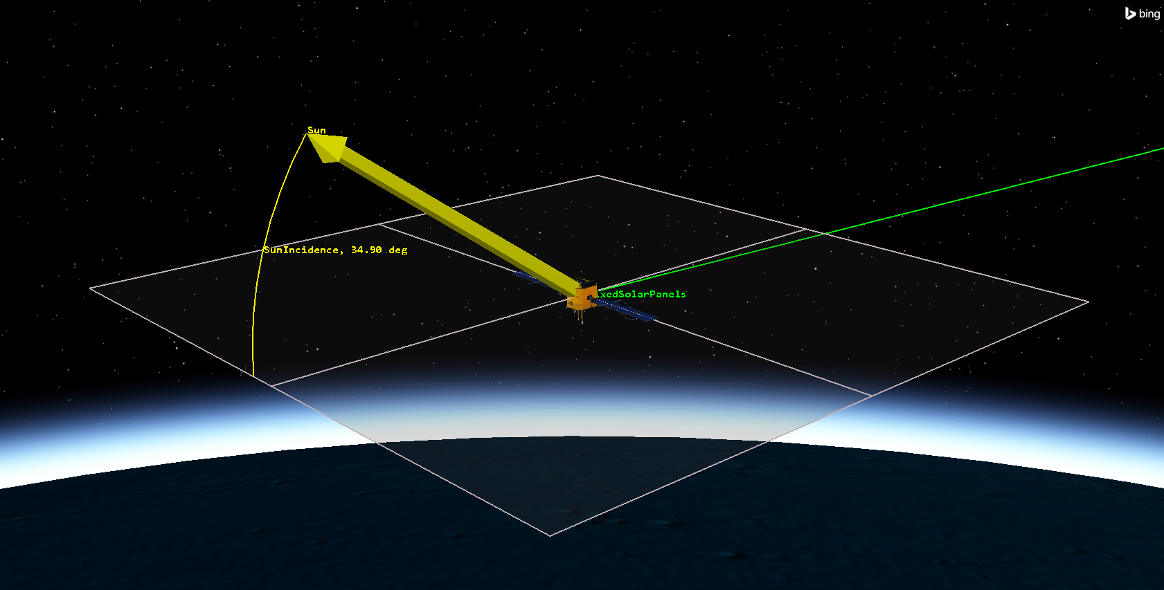
vector geometry components
The SunIncidence angle will vary over time, with positive or negative values depending on the relative position of the Sun with respect to the spacecraft. Also note that the solar panels are laying in the Body XY plane.
Using the Calculation tool
You now have a custom element (the Sun incidence angle), which you want to use to constrain the satellite's maneuvering. You only want the satellite to apply thrust when the Sun incidence angle is greater than zero, meaning when the Sun has a positive elevation with respect to the satellite Body XY plane. Use the Analysis Workbench capability to make that calculation.
- Right-click on FixedSolarPanels () in the Object Browser.
- Select Analysis Workbench... () in the shortcut menu.
- Select the Calculation tab in the Analysis Workbench.
Creating a scalar component
The Analysis Workbench capability's
- Click Create new Scalar Calculation (
 ) in the toolbar.
 - Notice that the default Type is set to Angle in the Add Calculation Component dialog box.
- Enter SunIncidence in the Name field.
The Angle scalar type is an angular displacement specified by an Angle component from the Vector Geometry Tool.
Choosing the input angle
Select the SunIncidence angle your created in the Vector Geometry Tool.
- Click the Input Angle ellipsis ().
- Select SunIncidence (
 ) in the Angle for: FixedSolarPanels list in the Select Reference Angle dialog box.
 - Click to accept your selection and to close the Select Reference Angle dialog box.
- Click to close the Add Calculation Component dialog box.
- Click to close the Analysis Workbench.
Defining an R Magnitude stopping condition
Set an R Magnitude stopping condition for the Propagate segment.
- Return to FixedSolarPanels' () Properties ().
- Select the Basic - Orbit page.
- Select the Propagate () segment in the MCS.
- Click New... () in the Stopping Conditions panel toolbar.
- Select R Magnitude () in the New Stopping Condition dialog box.
- Click to accept your selection and to close the New Stopping Condition dialog box.
Setting the R Magnitude stopping condition properties
An R Magnitude Trip value of 20,000 km will be the overall terminating distance for propagation.
- Enter 20000 km in the Trip field.
- Enter 1 km in the Tolerance field.
- Click to accept your changes and to keep the Properties Browser open.
Defining a UserSelect stopping condition
Add a UserSelect stopping condition, which will stop the propagation at a value defined by a calculation object.
- Click New... () in the Stopping Conditions panel toolbar.
- Select UserSelect () in the New Stopping Condition dialog box.
- Click to accept your selection and to close the New Stopping Condition dialog box.
Setting the UserSelect stopping condition properties
Many calculation objects are available for use with the Astrogator capability. Set your UserSelect stopping condition to use a scalar value, which can be based on any Calculation component from the Analysis Workbench.
- Double-click on UserSelect in the Name column.
- Enter NegativeSunAngle as the new name.
- Click User Calc Object - .
- Click when the User Calculation Object Selection dialog box opens.
- Expand () the Scalar () folder in the Component Link Selection dialog box.
- Select Scalar ().
- Click to accept your selection and to close the Component Link Selection dialog box.
Selecting the Scalar Calculation
Use the SunIncidence scalar calculation for the stopping condition.
- Double-click on the Scalar - Value cell.
- Open the Filter by drop-down list when the Select Reference dialog box opens.
- Select Satellite.
- Select FixedSolarPanels () in the object tree.
- Select SunIncidence () in the Scalar Calculations for: FixedSolarPanels list.
- Click to accept your selection and to close the Select Reference dialog box.
Setting the unit dimension
Change the unit dimension to use an angle unit. The default value is set to Unitless.
- Double-click on the UnitDimension - Value cell.
- Open the Selection drop-down list in the Listbox Field dialog box.
- Select AngleUnit.
- Click to accept your selection and to close the Listbox Field dialog box.
- Click to close the User Calculation Object Selection dialog box.
- Click to accept your changes and to keep the Properties Browser open.
Updating the NegativeSunAngle stopping condition
Update the NegativeSunAngle stopping condition's satisfaction criteria to use a Cross Increasing criterion. The Cross Increasing criterion means the stopping condition is satisfied when the parameter reaches a value equal to the trip value while increasing.
- Select the NegativeSunAngle stopping condition in the Stopping Conditions panel.
- Adjust the following settings:
- Select the Duration stopping condition.
- Click Delete () in the Stopping Conditions panel toolbar.
| Option | Value |
|---|---|
| Trip | 0 deg |
| Criterion | Cross Increasing |
| Tolerance | 0.1 deg |
Selecting the propagator
Select Earth Point Mass as the propagator.
- Click the Propagator ellipsis ().
- Select Earth Point Mass () in the Select Component dialog box.
- Click to accept your selection and to close the Select Component dialog box.
- Click to accept your changes and to keep the Properties Browser open.
Creating an Automatic Sequence
This Automatic Sequence segment will execute maneuvering only when the incidence angle between the Sun and the solar panels is positive.
- Click Automatic Sequence Browser () in the MCS toolbar.
- Click in the Automatic Sequence Browser dialog box.
- Enter SunlightManeuver in the Name field in the Field Editor dialog box.
- Click to accept your change and to close the Field Editor dialog box.
Editing the Automatic Sequence properties
Start by inserting a Maneuver segment.
- Select SunlightManeuver in the Automatic Sequence Browser dialog box.
- Click .
- Click Insert Segment After () in the Automatic Sequence Properties dialog box toolbar.
- Select Maneuver () in the Segment Selection dialog box.
- Click to accept your selection and to close the Segment Selection dialog box.
Editing the Maneuver segment
Change the Maneuver segment's color.
- Click Segment Properties () in the Automatic Sequence Properties dialog box toolbar.
- Enter SunConstrained in the Name field in the Edit Segment dialog box.
- Open the Color drop-down list.
- Select Red.
- Click to accept your selections and to close the Edit Segment dialog box.
Setting the maneuver type
Set the Maneuver segment to use a Finite maneuver type.
- Open the Maneuver Type drop-down list.
- Select Finite.
Updating the Finite Propagator and Force Model for Optimization
Set Earth Point Mass as the Maneuver segment's propagator.
- Click the ellipsis () next to the Finite Propagator and Force Model for Optimization field.
- Select Earth Point Mass () in the Select Component dialog box.
- Click to accept your selection and to close the Select Component dialog box.
Setting the maneuver to use Basic - Attitude
This will prevent the maneuver from defining the vehicle's attitude, allowing the SunIncidence angle to be applied.
- Select the Attitude tab.
- Click .
- Select the Use attitude page definition for other STK functions option in the More Attitude Options dialog box.
- Click to accept your selection and to close the More Attitude Options dialog box.
Selecting the Low Thrust engine model
Use your custom low-thrust engine model.
- Select the Engine tab.
- Click the Engine Model ellipsis () in the Propulsion Type panel.
- Select Low Thrust () in the Select Component dialog box.
- Click to accept your selection and to close the Select Component dialog box.
Creating a UserSelect stopping condition for the finite maneuver propagator
The next step is to create the proper stopping condition for the sun-constrained maneuver's propagator.
- Select the Propagator tab.
- Click New... () in the Stopping Conditions panel toolbar.
- Select UserSelect () in the New Stopping Condition dialog box.
- Click to accept your selection and to close the New Stopping Condition dialog box.
- Enter SunAngle in the UserSelect Name field.
Refining the stopping conditions
Set your UserSelect stopping condition to use a Scalar.
- Click .
- Select the SunAngle in the Stopping Condition panel in the MCSProp dialog box.
- Click User Calc Object - .
- Click in the User Calculation Object Selection dialog box.
- Expand () the Scalar () folder in the Component Link Selection dialog box.
- Select Scalar ().
- Click to accept your selection and to close the Component Link Selection dialog box.
Selecting the Scalar Calculation
Select the SunIncidence scalar for the stopping condition.
- Double-click on the Scalar - Value cell.
- Open the Filter by drop-down list in the Select Reference dialog box.
- Select Satellite.
- Select FixedSolarPanels () in the object tree.
- Select SunIncidence () in the Scalar Calculations for: FixedSolarPanels list.
- Click to accept your selection and to close the Select Reference dialog box.
Setting the unit dimension
Change the unit dimension of the scalar to AngleUnit.
- Double-click on the UnitDimension - Value cell.
- Open the Selection drop-down list in the Listbox Field dialog box.
- Select AngleUnit.
- Click to accept your selection and to close the Listbox Field dialog box.
- Click to close the User Calculation Object Selection dialog box.
Updating the SunAngle stopping condition
Update the SunAngle stopping condition's satisfaction criteria to use a Cross Decreasing criterion. The Cross Decreasing criterion means the stopping condition is satisfied when the parameter reaches a value equal to the trip value while decreasing.
- Select the SunAngle stopping condition.
- Set the following parameters:
- Select Duration in the Stopping Conditions panel.
- Click Delete () in the Stopping Conditions panel toolbar.
- Click to accept your changes and to close the MCSProp dialog box.
- Click to close the Automatic Sequence Properties dialog box.
- Click to close the Automatic Sequence Browser dialog box.
- Click to accept your changes and to keep the Properties Browser open.
| Option | Value |
|---|---|
| Trip | 0 deg |
| Criterion | Cross Decreasing |
| Tolerance | 0.1 deg |
Implementing the Automatic Sequence
You just created an Automatic Sequence that will execute maneuvering (using the custom low-thrust engine you previously defined) only when the Sun has a positive incidence angle with respect to the satellite's solar panels.
- Select the NegativeSunAngle stopping condition.
- Click the Sequence ellipsis ().
- Select SunlightManeuver () in the Select Component dialog box.
- Click to accept your selection and to close the Select Component dialog box.
- Click to accept your changes and to keep the Properties Browser open.
- Save () the scenario.
Running the entire Mission Control Sequence
With your Automatic Sequence and stopping conditions configured, run the entire Mission Control Sequence.
- Click Run Entire Mission Control Sequence () in the MCS toolbar.
- Click Clear Graphics ().
- Click to accept your changes and to close the Object Browser.
Viewing FixedSolarPanels' orbit in the 3D Graphics window
Look at your satellite's orbit in the orbit in the 3D Graphics window.
- Bring the 3D Graphics window to the front.
- Click Home View () in the 3D Graphics window toolbar.
- Use your mouse buttons to zoom out and rotate the view so get an idea of the colors in the orbit.
FixedSolarPanels' orbit
The red portion of the orbit is when the satellite executes its low-thrust maneuver. The green portion is when the satellite is in sunlight but with a negative solar incidence angle with respect to the solar panels.
Creating a Maneuver Summary report
Create an overview of the engine's performance with a Maneuver Summary report.
- Right-click on FixedSolarPanels () in the Object Browser.
- Select Report & Graph Manager... () in the shortcut menu.
- Select the Maneuver Summary () report in the My Favorites () folder in the Styles panel.
- Click .
- Scroll through the Maneuver Summary report.
- Close the report when finished viewing the data.
The maneuver durations increase as the satellite spirals outward and time spent in sunlight increases along with the period.
Graphing both satellites for comparison
Now, compare the semi-major axes of both satellites on a single graph.
- Select BodyInSunlight () and FixedSolarPanels () in the Object Type list.
- Select Semimajor Axis () in the My Styles () folder in the Styles panel.
- Click .
- Close any reports, graphs and the Report & Graph Manager when finished.
- Clear the FixedSolarPanels () check box in the Object Browser.
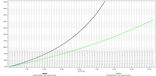
both Satellites comparison graph
Since the incidence angle constraint for FixedSolarPanels is more stringent than BodyInSunlight, whose condition is that it be only be in sunlight, the orbit is more elliptical than in the previous case and the overall semi-major axis value does not grow as high.
Modeling a satellite using Sun constraints
For this next iteration, you have a more stringent operative requirement: a minimum available power output from the solar panels during the maneuvering period. Since the available power for the solar panels is not a default data provider in the STK software, you will use the Analysis Workbench capability to create a custom data provider. Specifically, you will use a script that takes the Sun incidence angle as input and provides the power as an output. The script will use this well-known formula to calculate the power:

You will see how to implement the script later. Begin by creating and configuring a new satellite.
Inserting a third Satellite object
Insert another Satellite object to model a power-constrained satellite.
- Insert a Satellite () object using the Insert Default () method.
- Rename Satellite3 () PowerConstraint.
Set PowerConstraint's propagator to Astrogator
As before, use Astrogator to design the satellite's trajectory.
- Open PowerConstraint's () Properties ().
- Select the Basic - Orbit page.
- Open the Propagator drop-down list.
- Select Astrogator.
Modifying the graphics for situational awareness
Modify the graphics settings so that you can view the satellite's entire orbit. Specifically, you want to see when a portion of the orbit is in Umbra.
- Select the to the 3D Graphics - Pass page.
- Open the Lead Type drop-down list in the Orbit Track panel.
- Select All.
- Select the 2D Graphics - Lighting page.
- Select the Umbra check box.
- Click to accept your changes and to keep the Properties Browser open.
Locking the solar panels to a fixed orientation
Like in the previous case, you need to lock the solar panels in place with respect to the satellite body axis.
- Select the 3D Graphics - Model Pointing page.
- Select None in the Available Targets panel.
- Click to accept your changes and to keep the Properties Browser open.
Setting an Articulation - Transformation value
Modify the articulations of the satellite's 3D model that contains articulations and transformations.
- Select the 3D Graphics - Model page.
- Click in the Articulations panel.
- Select SolarPanels in the Articulations panel in the Model Articulations dialog box.
- View the Transformations - Rotate setting and modify it to 0 if needed.
- Click to close the Model Articulations dialog box.
- Click to accept your changes and to keep the Properties Browser open.
The value should be set to 0 since you already modified this 3D model earlier in the tutorial.
Defining the initial state
Set the orbital properties for the satellite.
- Select the Basic - Orbit page.
- Select the Initial State () segment in the MCS.
- Select the Elements tab.
- Open the Coordinate Type drop-down list.
- Select Keplerian.
- Set the following orbital element parameters:
- Leave the rest of the orbital elements at their default values.
- Click to accept your changes and to keep the Properties Browser open.
| Option | Value |
|---|---|
| Semi-major Axis | 7000 km |
| Eccentricity | 0 |
Running the entire Mission Control Sequence
Run the MCS to propagate the satellite using the default stopping conditions.
- Click Run Entire Mission Control Sequence () in the MCS toolbar.
- Click Clear Graphics () in the MCS toolbar.
- Click to accept your changes and to keep the Properties Browser open.
Using the Vector Geometry tool
Create a new angle component using the Analysis Workbench capability to evaluate when the solar incidence angle with the solar panels is greater than zero.
- Right-click on PowerConstraint () in the Object Browser.
- Select Analysis Workbench... () in the shortcut menu.
- Select the Vector Geometry tab when the Analysis Workbench opens.
Creating a custom angle component
Create a new To Plane angle component. The To Plane type defines an angle between a vector and a plane.
- Click Create New Angle () in the Vector Geometry toolbar.
- Click Type - in the Add Geometry Component dialog box.
- Select To Plane () in the Select Component Type list in the Select Component Type dialog box.
- Click to accept your selection and to close the Select Component Type dialog box.
- Enter SunIncidence in the Name field.
Setting the To Plane angle properties
Compute the To Plane angle using the Signed option so that it can be measured as Negative when the reference Vector is directed toward the plane’s normal.
- Click the Reference Vector ellipsis ().
- Select PowerConstraint () in the object tree in the Select Reference Vector dialog box.
- Select Sun () in the Vectors for: PowerConstraint list.
- Click to accept your selection and to close the Select Reference Vector dialog box.
- Keep the default Reference Plane setting of PowerConstraint Body.XY.
- Select the Signed check box.
- Open the Toward plane normal drop-down list.
- Select Negative.
- Click to accept your changes and to close the Add Geometry Component dialog box.
Using the Calculation tool
You now have a custom Vector Geometry component available. The next step is to create an additional scalar element that uses the value of the Vector Geometry component, which you will use in creating a custom VBScript file.
- Select the Calculation tab using the Analysis Workbench capability.
- Select PowerConstraint () in the object tree of the Calculation tool.
Creating a Scalar Calculation component
Create a new Scalar Calculation component.
- Click Create new Scalar Calculation () in the toolbar.
- Use the default Angle type in the Add Calculation Component dialog box.
- Enter SunIncidence in the Name field.
The Angle type is an angular displacement specified by an Angle component from the Vector Geometry Tool.
Choosing the input angle
Select the SunIncidence angle your created in the Vector Geometry Tool.
- Click the Input Angle ellipsis ().
- Select SunIncidence () in the Angle for: PowerConstraint list in the Select Reference Angle dialog box.
- Click to accept your selection and to close the Select Reference Angle dialog box.
- Click to close the Add Calculation Component dialog box.
Using VBScript as input for a Custom Scalar Calculation
Here are a couple of basic considerations:
- The script must be located inside a specific sub-folder of the main scenario folder.
- The input variables in the script will be scalar components in the STK scenario; in this case, you'll use the SunIncidence scalar that you just created.
The SunIncidence angle will be the input for your script that will calculate the amount of power available to the solar panels. This variable will then be used to trigger the finite maneuver.
Creating a path to store a VBScript file
Script files that are to be used with Custom Scalar Calculations must be located in the proper directory. The STK application will check for the VBScript file in a folder called Scalar.
- Navigate to your scenario folder using Windows File Explorer.
- Create a new folder named Scripting.
- Open the Scripting folder.
- Create a new folder named VectorTool.
- Open the VectorTool folder.
- Create a new folder named Scalar.
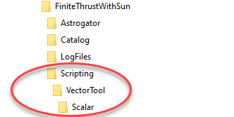
folder structure
A nested folder structure
Creating the VBScript file
Create your VBScript file using Windows Notepad or a text editor of your choice that doesn't insert hidden characters.
- Open your text editor.
- Copy and paste the following script into your text editor:
Dim AvailablePower_compute_init
					Dim AvailablePower_Inputs
					Dim AvailablePower_Outputs

					Function AvailablePower(argArray)

					Dim retVal
					If IsEmpty(argArray(0)) Then
					retVal = AvailablePower_compute(argArray)
					ElseIf argArray(0) = "register" Then
					AvailablePower_compute_init = -1
					retVal = AvailablePower_register()
					ElseIf argArray(0) = "compute" Then
					retVal = AvailablePower_compute(argArray)
					Else
					retVal = Empty
					End If
					AvailablePower = retVal

					End Function

					Function AvailablePower_register()

					ReDim argStr(2)
					argStr(0) = "ArgumentType = Output ; Name = Scalar ; ArgumentName = value"
					argStr(1) = "ArgumentType = Input ; Type = Scalar ; Source = Satellite/PowerConstraint ; Name = SunIncidence ; ArgumentName = SunIncidence"
					AvailablePower_register = argStr

					End Function

					Function AvailablePower_compute(stateData)

					If AvailablePower_compute_init < 0 Then
					Set AvailablePower_Inputs = g_GetPluginArrayInterface("AvailablePower_Inputs")
					Set AvailablePower_Outputs = g_GetPluginArrayInterface("AvailablePower_Outputs")
					AvailablePower_compute_init = 1
					End If

					ReDim returnValue(1)
					returnValue(AvailablePower_Outputs.value) = CustomScalar(stateData(AvailablePower_Inputs.SunIncidence))
					AvailablePower_compute = returnValue

					End Function

					Function CustomScalar(SunIncidence)
					If SunIncidence > 0 Then
					CustomScalar = 1380*sin(SunIncidence)
					Else
					CustomScalar = 0
					End If
				End Function
Saving the VBScript file
Save the script file from your text editor in the Scalar folder you created earlier.
- Select Save As... in the file menu.
- Navigate to the Scalar folder you created earlier.
- Select All Files from the Save as Type drop-down list.
- Enter AvailablePower.vbs in the File name field.
- Click .
- Close the text editor and Windows File Explorer.
The file name is the same as the function name in the script.
Creating a new Scalar Calculation component
Use the custom VBScript file to create a new Scalar Calculation.
- Return to the Analysis Workbench.
- Select PowerConstraint () in the object tree.
- Click Create New Scalar Calculation () in the Calculation Tool toolbar.
Using the custom VBScript file for a Scalar Calculation
Use your VBScript file in the Calculation component of your scalar calculation by selecting the Custom Script scalar calculation type. The Custom Script type is a custom scalar calculation implemented using a script written in the MATLAB, Python, or VBScript scripting language.
- Click Type - in the Add Calculation Component dialog box.
- Select Custom Script () in the Select Component Type list in the Select Component Type dialog box.
- Click to accept your selection and to close the Select Component Type dialog box.
Setting the Calculation component's properties
Update the Calculation component to utilize the VBScript file.
- Enter AvailablePower in the Name field.
- Click the CalcScalar Script File ellipsis ().
- Browse to the Scalar folder where you stored the VBScript (e.g. C:\Users\<username>\Documents\STK_ODTK 13\FiniteThrustWithSun\Scripting\VectorTool\Scalar).
- Select AvailablePower.vbs.
- Click .
- Open the Dimension drop-down list.
- Select Power.
- Click to accept your changes and to close the Add Calculation Component dialog box.
Checking the available power over time
All components from the Time and Calculation Tools of the Analysis Workbench capability have on-the-spot, right-click, reporting options without first having to create new report or graph style. With this functionality, you can create reports and graphs inside the Analysis Workbench. Use this functionality to create a graph of the power available to the satellite over time.
- Right-click on AvailablePower () in the Components for: PowerConstraint list.
- Select Report/Graph... in the shortcut menu.
- Open the Type drop-down list in the Report/Graph Details panel in the Calculation Report/Graph dialog box.
- Select Graph.
- Select AvailablePower () in the Select Graph Elements list.
- Click .
Changing the graph's units
Change the display unit of the dependent variable from decibel Watts (dbW) to Watts (W).
- Click Graph Units (
 ) in the graph toolbar.
 - Select Power in the Dimension list in the Units: AvailablePower dialog box.
- Select Watts (W) in the New Unit Value list.
- Click to accept your change and to close the Units: AvailablePower dialog box.
- When finished, close () the AvailablePower graph.
- Click to close the Calculation Report/Graph dialog box.
- Click to close the Analysis Workbench.
Note the dependent variable is displayed in Watts and is consistent with the incidence angle.
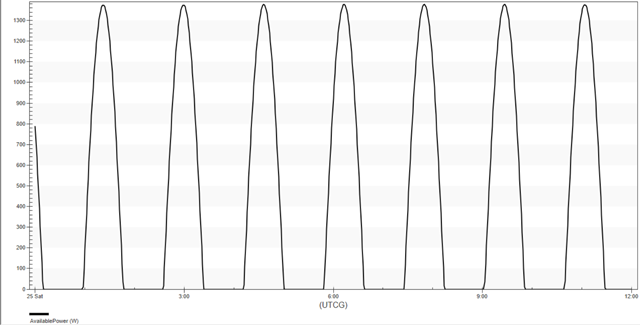
available power graph
Defining the stopping conditions
This R Magnitude stopping condition will be the overall terminating event for the Propagate segment, as with the other satellite iterations.
- Return to PowerConstraint's () Properties ().
- Select the Propagate () segment in the MCS.
- Click New... () in the Stopping Conditions panel toolbar.
- Select R Magnitude () in the New Stopping Condition dialog box.
- Click to accept your selection and to close the New Stopping Condition dialog box.
Setting an R Magnitude stopping condition properties
As before, set the Trip value to 20,000 km for the R Magnitude stopping condition to create a baseline for comparison.
- Enter 20000 km in the Trip field.
- Enter 1 km in the Tolerance field.
- Click to accept your changes and to keep the Properties Browser open.
Selecting a UserSelect stopping condition
Create a UserSelect stopping condition for the power-constrained maneuver's propagator.
- Click New... () in the Stopping Conditions panel toolbar.
- Select UserSelect () in the New Stopping Condition dialog box.
- Click to accept your selection and to close the New Stopping Condition dialog box.
Setting the UserSelect stopping condition properties
Update the stopping condition's properties to utilize a Scalar.
- Double-click on the UserSelect Name cell.
- Enter LessPower as the new name.
- Click User Calc Object - .
- Click in the User Calculation Object Selection dialog box.
- Expand () the Scalar () folder in the Component Link Selection dialog box.
- Select Scalar ().
- Click to accept your selection and to close the Component Link Selection dialog box.
Using the AvailablePower Scalar for the UserSelect stopping condition
Set the Scalar stopping condition to use the AvailablePower Scalar Calculation you created.
- Double-click on the Scalar - Value cell.
- Open the Filter by drop-down list in the Select Reference dialog box.
- Select Satellite.
- Select PowerConstraint () in the object tree.
- Select AvailablePower (
 ) in the Scalar Calculations for: PowerConstraint list.
 - Click to accept your selection and to close the Select Reference dialog box.
Setting the unit dimension
Change the unit dimension of the scalar to PowerUnit.
- Double-click on the UnitDimension - Value cell.
- Open the Selection drop-down list of the Listbox Field dialog box.
- Select PowerUnit.
- Click to close the Listbox Field dialog box.
- Click to close the User Calculation Object Selection dialog box.
- Click to accept your changes and to keep the Properties Browser open.
Updating the LessPower stopping condition
Update the LessPower stopping condition's satisfaction criteria.
- Select the LessPower stopping condition.
- Enter 500 W in the Trip field.
- Enter 1 W in the Tolerance field.
- Open the Criterion drop-down list.
- Select Cross Increasing.
- Select the Duration stopping condition.
- Click Delete () in the Stopping Conditions panel toolbar.
Changing the propagator
Change the propagator to Earth Point Mass.
- Click the Propagator ellipsis ().
- Select Earth Point Mass () in the Select Component dialog box.
- Click to accept your selection and to close the Select Component dialog box.
Creating an Automatic Sequence
Create an Automatic Sequence that will enable engine thrust only when the available power from the solar panels is higher than a specific threshold.
- Click Automatic Sequence Browser () in the MCS toolbar.
- Click in the Automatic Sequence Browser dialog box.
- Enter PowerManeuver in the Name field of the Field Editor dialog box.
- Click to accept your change and to close the Field Editor dialog box.
Editing the PowerManeuver Automatic Sequence
Insert a new Maneuver segment into the Automatic Sequence.
- Select PowerManeuver in the Automatic Sequence Browser dialog box.
- Click .
- Click Insert Segment After () in the Automatic Sequence Properties dialog box.
- Select Maneuver () in the Segment Selection dialog box.
- Click to accept your selection and to close the Segment Selection dialog box.
Setting the Maneuver segment color
Change the color of the Maneuver segment to red.
- Click Segment Properties () in the Automatic Sequence Properties dialog box toolbar.
- Enter PowerConstrained in the Name field of the Edit Segment dialog box.
- Open the Color drop-down list.
- Select Red.
- Click to accept your changes and to close the Edit Segment dialog box.
Updating the maneuver type and propagator
Select Earth Point Mass as the Finite Propagator.
- Open the Maneuver Type drop-down list.
- Select Finite.
- Click the ellipsis () next to the Finite Propagator and Force Model for Optimization field.
- Select Earth Point Mass () in the Select Component dialog box.
- Click to accept your selection and to close the Select Component dialog box.
Setting the attitude
Use the attitude page definition for other STK functions.
- Select the Attitude tab.
- Use the default Attitude settings.
- Click .
- Select the Use attitude page definition for other STK functions option when the More Attitude Options dialog box opens.
- Click to accept your selection and to close the More Attitude Options dialog box.
Selecting the custom Low Thrust engine model
Use your custom Low Thrust engine model to execute the maneuver.
- Select the Engine tab.
- Click the Engine Model ellipsis () in the Propulsion Type panel.
- Select Low Thrust () in the Select Component dialog box.
- Click to accept your selection and to close the Select Component dialog box.
Creating a UserSelect stopping condition
You just defined a new Automatic Sequence. The next step is to create the proper stopping condition for the maneuver's propagator.
- Select the Propagator tab.
- Click New... () in the Stopping Conditions panel toolbar.
- Select UserSelect () in the New Stopping Condition dialog box.
- Click to accept your selection and to close the New Stopping Condition dialog box.
Editing the UserSelect stopping condition
Rename the UserSelect stopping condition.
- Double-click on the UserSelect stopping condition Name cell.
- Enter MorePower.
Selecting a Scalar component
Set the MorePower stopping condition to use a Scalar component.
- Click .
- Select the MorePower stopping condition.
- Click User Calc Object - .
- Click in the User Calculation Object Selection dialog box.
- Expand () the Scalar () folder in the Component Link Selection dialog box.
- Select Scalar ().
- Click to accept your selection and to close the Component Link Selection dialog box.
Selecting and configuring the scalar
Set the Scalar stopping condition to use the AvailablePower Scalar Calculation you created.
- Double-click on the Scalar - Value cell.
- Open the Filter by drop-down list in the Select Reference dialog box.
- Select Satellite.
- Select PowerConstraint () in the object tree.
- Select AvailablePower () in the Scalar Calculations for: PowerConstraint list.
- Click to accept your selection and to close the Select Reference dialog box.
Setting the unit dimension
Change the unit dimension of the scalar to PowerUnit.
- Double-click on the UnitDimension - Value cell.
- Open the Selection drop-down list in the Listbox Field dialog box.
- Select PowerUnit.
- Click to close the Listbox Field dialog box.
- Click to close the User Calculation Object Selection dialog box.
Updating the MorePower stopping condition properties
Update the MorePower stopping condition's satisfaction criteria so that it will apply thrust (using the custom engine you previously defined) only when the solar panels can provide power higher than 500 W.
- Enter 500 W in the Trip field.
- Enter 1 W in the Tolerance field.
- Open the Criterion drop-down list.
- Select Cross Decreasing.
- Select the Duration stopping condition.
- Click Delete () in the Stopping Conditions panel toolbar.
- Click to accept your changes and to close the MCSProp dialog box.
- Click to close the Automatic Sequence Properties dialog box.
- Click to close the Automatic Sequence Browser dialog box.
- Click to accept your changes and to keep the Properties Browser open.
Implementing the Automatic Sequence
With your Automatic Sequence set up, set the stopping condition to utilize it.
- Select the LessPower stopping condition.
- Click the Sequence ellipsis ().
- Select PowerManeuver () in the Select Component dialog box.
- Click to accept your selection and to close the Select Component dialog box.
Running the entire Mission Control Sequence
You're now ready to propagate the MCS using the PowerManeuver Automatic Sequence.
- Click Run Entire Mission Control Sequence () in the MCS toolbar.
- Click Clear Graphics () in the MCS toolbar.
- Click to accept your changes and to close the Properties Browser.
Viewing PowerConstraint's orbit in the 3D Graphics window
Review the PowerConstraint satellite's orbit in the 3D Graphics window.
- Bring the 3D Graphics window to the front.
- Click Home View () in the 3D Graphics window toolbar.
- Use your mouse to obtain a good view of PowerConstraint's () orbit.
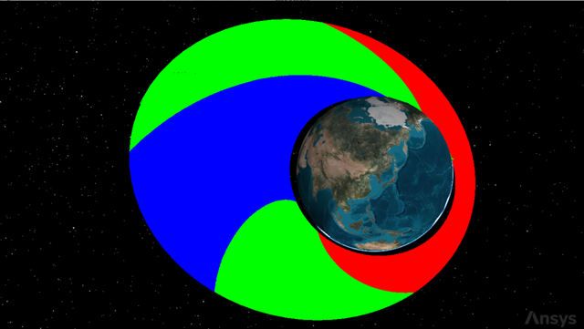
Powerconstraint's orbit
The red portion of the orbit is when the satellite executes its low-thrust maneuver when the solar panel power is 500 watts or greater. The green portion is when the satellite is in sunlight but with an available power less than 500 watts.
Creating a Maneuver Summary report
Create an overview of the engine's performance.
- Right-click on PowerConstraint () in the Object Browser.
- Select Report & Graph Manager... () in the shortcut menu.
- Select the Maneuver Summary () report in the My Favorites () folder in the Styles panel.
- Click .
- Scroll through the Maneuver Summary report.
- Close the report when finished viewing the data.
The maneuver durations increase as the satellite spirals outward and time spent in sunlight increases along with the period.
Graphing all three satellites for comparison
Finally, compare the semi-major axes of all three satellites in your scenario.
- Select BodyInSunlight (), FixedSolarPanels () and PowerConstraint () in the Object Type list.
- Select Semimajor Axis () in the My Styles () folder in the Styles panel.
- Click .
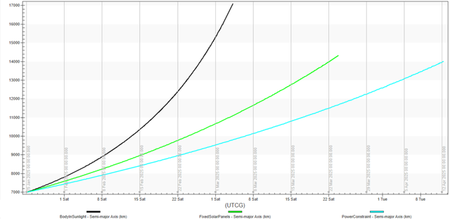
Satellite comparison graph
Since the incidence angle constraint for PowerConstraint is more stringent than both BodyInSunlight and FixedSolarPanels, the orbit is more elliptical than in the previous cases and the overall value of the semi-major axis does not grow as high.
Saving your work
Clean up your workspace and save your work.
- Close any open reports, properties and tools.
- Save () your work.
Summary
The exercises in this scenario aimed to design and implement constraints relevant to different scalar elements to use with lighting conditions and Automatic Sequences. When a data provider element is not directly available in the STK software, it can be built using different approaches using the Analysis Workbench capability.