STK Pro, STK Premium (Air), STK Premium (Space), or STK Enterprise
You can obtain the necessary licenses for this tutorial by contacting AGI Support at support@agi.com or 1-800-924-7244.
The results of the tutorial may vary depending on the user settings and data enabled (online operations, terrain server, dynamic Earth data, etc.). It is acceptable to have different results.
Capabilities covered
This lesson covers the following capability of the Ansys Systems Tool Kit® (STK®) digital mission engineering software:
- STK Pro
Problem statement
Engineers and operators need a way to display a large amount of data within an STK scenario for efficient visualization purposes. Such tracks of time-dependent positional data points — tracks like the flights paths of aircraft, the tracks of ground vehicles, test measurements, and the positions of facilities and other objects — can add valuable context to the broader mission environment. Because the STK application automatically computes data such as To Vectors and Lighting Intervals for all STK objects in a scenario, defining them as individual, analytical STK objects can unnecessarily increase the file size of the scenario as well as computation times. You need a way to visualize such assets without adding needless complexity to your scenario; in this case, you want to visualize the routes of two "blue" vehicles and two "red" vehicles over time.
Solution
Use a Multi-Track Object (MTO) to group together many moving or stationary objects to display a large amount of non-analytical data within a scenario. Understanding MTOs is a key prerequisite for organizing track measurements in the
What you will learn
Upon completion of this tutorial, you will be able to:
- Create an MTO using the graphical user interface (GUI)
- Change the appearance of MTO tracks in the 2D Graphics window
- Modify the view of an MTO in the 3D Graphics window
Creating a new scenario
First, you must create a new scenario, then build from there.
- Launch the STK (
 ) application.
 - Click
 Create a Scenario in the Welcome to STK dialog box.
 - Enter the following in the New Scenario Wizard:
Option Value Name MTO_Scenario Location Default Start Date: Default / Time: 17:00:00.000 UTCG Stop + 10000 sec - Click when you finish.
- Click Save (
 ) when the scenario loads.
 - Verify the scenario name and location when the Save As dialog box opens.
- Click .
The STK application automatically creates a folder with the same name as your scenario for you.
Changing the date format
Change the scenario's date format to epoch seconds by updating its
- Right-click on MTO_Scenario () in the Object Browser.
- Select Properties (
 ) in the shortcut menu.
 - Select the Basic - Units page when the Properties Browser opens.
- Click on DateFormat - Current Unit (for example, Gregorian UTC (UTCG)) in the Dimension List panel.
- Open the Current Unit drop-down list.
- Select Epoch Seconds (EpSec).
- Select the Tab key.
- Click to confirm your change and to keep the Properties Browser open.
The epoch is calculated as time elapsed relative to the scenario epoch.
Turning off streaming terrain
You will not be using terrain analytically in this scenario, so you can disable streaming terrain. This will also allow the tracks to be displayed more clearly on the surface of the default WGS84 ellipsoid.
- Select the Basic - Terrain page.
- Clear the Use terrain server for analysis check box in the Terrain Server panel.
- Click to confirm your change and to close the Properties Browser.
Configuring the 2D Graphics window properties
Configure the 2D Graphics window for a simpler display by updating its
- Bring the 2D Graphics window to the front.
- Click Properties () on the 2D Graphics window's 2D Window Defaults toolbar.
- Select the Imagery page when the Properties Browser opens.
- Clear the Show check box in the Background Image panel.
- Select the Details page.
- Click to select the following options in the Map Details panel:
- RWDB2_Coastlines (selected by default)
- RWDB2_International_Borders
- RWDB2_Islands
- RWDB2_Lakes
- Click to confirm your changes and to close the Properties Browser.
Creating a Multi-Track Object
Insert a Multi-Track Object into the scenario. A
Displaying the Multi-Track Object in the Insert STK Objects tool
You must first add the Multi-Track Object to the Insert STK Objects tool to be able to insert it into your scenario.
- Bring the Insert STK Objects (
 ) tool to the front.
 - Click .
- Ensure the New Object page is selected when the Preferences dialog box opens.
- Select the Show check box for the MTO Object in the Define Default Creation Methods panel.
- Click to confirm your selection and to close the Preferences dialog box.
Inserting a new Multi-Track Object
Insert a new Multi-Track Object.
- Select MTO (
 ) in the Select An Object to Be Inserted list.
 - Select Insert Default () in the Select A Method list.
- Click .
Creating new tracks
Data sets are organized into tracks. Add four tracks to your MTO on the
- Open MTO1's () Properties ().
- Select the Basic - Tracks page when the Properties Browser opens.
- Click four times to add four tracks to the Track table.
The Track table lists the tracks created in the MTO object, and gives basic information about each. You should have four tracks; each has an ID number, which cannot be modified, auto-populated in sequential numeric order.
Modifying a track
- Select the first track (Id: 1) in the Track table.
- Click .
- Enter Blue Ship in the Name field when the Modify Track Data dialog box opens.
- Click in the Points panel.
- Double-click on the appropriate field in the Points table to enter the following data. Select the tab key after each input:
- Click to create a second point.
- Set the following values for the second point:
- Select the Interpolate Position check box.
- Click to confirm your changes and to close the Modify Track Data dialog box.
- Click to confirm your changes and to keep the Properties Browser open.
If desired, the track name, as a label, can be displayed in the 2D and 3D Graphics windows, along with a track marker.
| Option | Value |
|---|---|
| Time | 0.0 EpSec |
| Latitude | 42.4 deg |
| Longitude | -86.6 deg |
| Altitude | 0 km |
| Option | Value |
|---|---|
| Time | 10000 EpSec |
| Latitude | 43.1 deg |
| Longitude | -86.5 deg |
| Altitude | 0 km |
The track's marker and label position will be linearly interpolated between the track points for the current animation time, producing a smoother animation.
Viewing the Blue Ship track in the 2D Graphics window
Take a look at the track of the Blue Ship.
- Bring the 2D Graphics window to the front.
- Zoom in on the Great Lakes region of the United States.
- Click Start (
 ) on the Animation toolbar.
 - Click Reset (
 ) when you are finished.
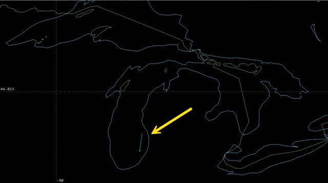
blue ship location
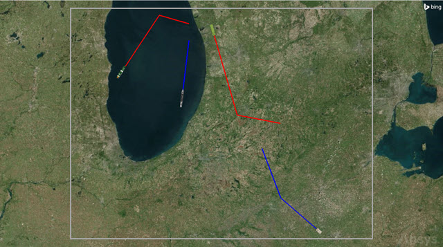
You should see a point marker representing the Blue Ship moving in a northeasterly direction along a track on the eastern side of Lake Michigan.
Modifying the other three MTO tracks
Add the other three tracks to your MTO.
- Return to MTO1's () Properties ().
- Using the same procedure as with the Blue Ship track, modify the other tracks as follows:
- After inserting all of the track points, click to confirm your changes and to keep the Properties Browser open.
- Bring the 2D Graphics window to the front.
- Click Start () on the Animation toolbar.
- Click Reset () when you are finished.
The STK application will automatically rearrange the points by time, so after entering the data for point #2, for example, it may jump to the #3 position.
| Track Id | Name | Point | Time | Latitude | Longitude | Altitude | Interpolate Position |
|---|---|---|---|---|---|---|---|
| 2 | Red Ship | 1 | 0.0 EpSec | 42.7 deg | -87.6 deg | 0 km | Selected |
| 2 | 6000 EpSec | 43.4 deg | -87.0 deg | 0 km | |||
| 3 | 10000 EpSec | 43.3 deg | -86.5 deg | 0 km | |||
| 3 | Blue Truck | 1 | 0 EpSec | 40.8 deg | -84.4 deg | 0 km | Selected |
| 2 | 5000 EpSec | 41.2 deg | -85.0 deg | 0 km | |||
| 3 | 10000 EpSec | 41.8 deg | -85.3 deg | 0 km | |||
| 4 | Red Truck | 1 | 0 EpSec | 43.2 deg | -86.1 deg | 0 km | Selected |
| 2 | 7000 EpSec | 42.2 deg | -85.7 deg | 0 km | |||
| 3 | 10000 EpSec | 42.1 deg | -85.0 deg | 0 km |
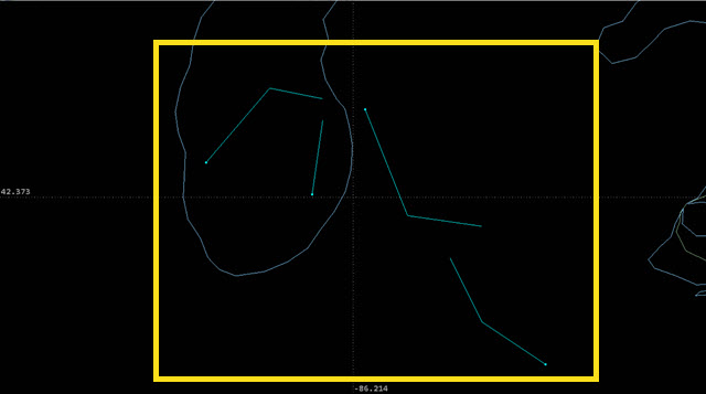
markers and tracks
You should now see simple point markers and tracks for all four of your objects move along the paths you defined in each MTO track.
Though you have manually defined the MTO tracks in this scenario, you can also load an ephemeris file (*.e) to define the points for an individual track. You can also modify MTO positions and properties through automated processes interacting with the STK application, such as those associated with the TETK and RT3 capabilities.
Configuring the 2D Graphics Track Attributes
Make the MTO graphics easier to see and understand by updating the MTO's
Changing all the tracks' line widths
Make each track's lines thicker by selecting all the tracks and opening the
- Return to MTO1's () Properties ().
- Select the 2D Graphics – Track Attributes page.
- Click .
- Click .
- Open the Line Width drop-down list in the Track Line panel when the Modify Track Graphics Data dialog box opens.
- Select 3.
- Click to confirm your selection and close the Modify Track Graphics Data dialog box dialog box.
- Click to confirm your change and to keep the Properties Browser open.
Changing marker styles
To make it easier to identify the types of objects represented in the 2D Graphics window, you can also change their marker styles.
- Use Ctrl+Click to
- Click .
- Open the Marker Style drop-down list when the Modify Track Graphics Data dialog box opens.
- Select the Ship (
 ) icon.
 - Click to confirm your selection and to close the Modify Track Graphics Data dialog box.
- Multi-select both the Blue Truck and Red Truck tracks in the Track table.
- Click .
- Open the Marker Style drop-down list when the Modify Track Graphics Data dialog box opens.
- Select the Ground Vehicle (
 ) icon.
 - Click to confirm your selection and to close the Modify Track Graphics Data dialog box.
- Click to confirm your changes and to keep the Properties Browser open.
Changing the "blue" vehicles' track colors
You can use color to distinguish between the "blue" and "red" vehicles. Start with the "blue" vehicles.
- Multi-select both the Blue Ship and Blue Truck tracks in the Track table.
- Click .
- Open the Color drop-down list when the Modify Track Graphics Data dialog box opens.
- Select blue.
- Click to confirm your selection and to close the Modify Track Graphics Data dialog box.
- Click to confirm your changes and to keep the Properties Browser open.
Changing the "red" vehicles' track colors
Now, repeat the process for the "red" vehicles.
- Multi-select both the Red Ship and Red Truck tracks in the Track table.
- Click .
- Open the Color drop-down list when the Modify Track Graphics Data dialog box opens.
- Select red.
- Click to confirm your selection and to close the Modify Track Graphics Data dialog box.
- Click to confirm your changes and to keep the Properties Browser open.
Viewing the tracks in the 2D Graphics window
View the tracks of the MTO in the 2D Graphics window.
- Bring the 2D Graphics window to the front.
- Click Start () on the Animation toolbar.
- Click Reset () when you are finished.
2D View of the MTO paths
You should now see two Ship markers and two Ground Vehicle markers and their tracks.
You can also display lines between a Scenario object and tracks in an MTO (and between tracks inside an MTO) by updating the
Configuring the 3D Graphics Track Attributes
You can replace the object markers with models of the ships and ground vehicles in the 3D Graphics window with 3D models by updating the MTO's 3D Graphics Track Attributes.
Updating the 3D Graphics track attributes
The
- Return to MTO1's () Properties ().
- Select the 3D Graphics – 3D Track Attributes page.
- Select the Blue Ship track in the Track 3D table.
- Click .
Modifying the 3D Track graphics
The
- Select the Show check box in the Model panel when the Modify Track 3D Graphics Data dialog box opens.
- Click the Model File ellipsis (
 ).
). - Open the Sea folder (<Install Dir>\STKData\VO\Models\Sea) when the File dialog box opens.
- Select ship.glb.
- Click to confirm your selection and to close the File dialog box.
- Set the Log Scale to 2.2.
- Clear the Z Points toward Nadir check box.
- Click to confirm your changes and to close the Modify Track 3D Graphics Data dialog box.
- Repeat the above procedure to modify the settings for the other tracks as follows:
- Click to confirm your changes and to keep the Properties Browser opens.
This will orient the 3D model as a surface vehicle.
| Track Id | Name | Model - Show | Model File | Log Scale | Z Points Toward Nadir |
|---|---|---|---|---|---|
| 2 | Red Ship | Selected | <Install Dir>\STKData\VO\Models\Sea\cruise_liner.glb | 2.0 | Cleared |
| 3 | Blue Truck | Selected | <Install Dir>\STKData\VO\Models\Land\humvee.glb | 3.2 | Cleared |
| 4 | Red Truck | Selected | <Install Dir>\STKData\VO\Models\Land\military-truck.glb | 3.2 | Cleared |
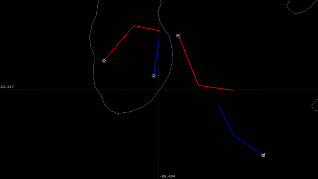
The 3D Graphics window now shows models for the objects instead of the 2D points used previously.
Setting the view to an MTO track
You can use the
- Select the Basic – Tracks page.
- Set the Computation Track Id to 3.
- Click to confirm your change and close the Properties Browser.
- Bring the 3D Graphics window to the front.
- Click View From/To (
 ) on the 3D Graphics window's 3D Graphics toolbar.
 - Select MTO1 () in the From Position field when the View From/To: 3D Graphics 1 - Earth dialog box opens.
- Click to confirm your selection and to close the View From/To: 3D Graphics 1 - Earth dialog box.
- Move around in the 3D Graphics window to get a view of the tracks and models.
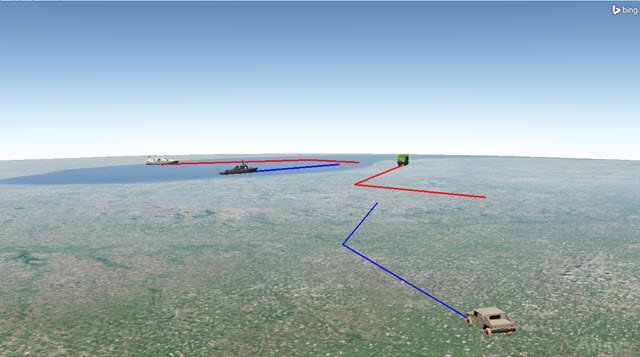
3D View of the MTO paths and Models
The view will be centered on the Blue Truck, which is track number 3. By changing the Computation Track Id, you can change which path the view will be centered on when selecting the MTO as the View From/To object.
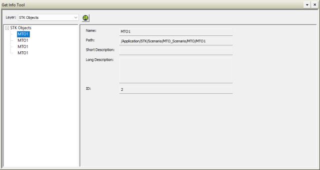
Using the Get Info tool with Multi-Track Objects
The
- Zoom out on the 3D Graphics window so that you can see all four (4) tracks.
- Select Utilities in the Menu Bar.
- Select Get Info Tool... (
 ) in the Utilities menu.
 - Click Enable object selection pick in 3D window (
 ) when the Get Info Tool window opens.
 - Click and hold in the 3D Graphics window to draw a rectangular selection box around all four tracks.
- Select one of the MTO1 entries in the STK Objects list in the Get Info Tool.
- View details about the track in the right-hand panel.
Get Info Tool: Object Selection Box
Get Info tool: MTO tracks
Note the track ID is displayed along with other information about the track.
When an MTO is part of the RT3 layer, you can use the Get Info tool to promote a selected track to a "heavy" STK object to analyze its data or demote a track back to an MTO.
Saving your work
Clean up your workspace and close out your scenario.
- Close the Get Info tool
- Save () your work.
- Close the scenario when you are finished.
Summary
This tutorial provided a basic introduction to Multi-Track Objects the STK application. You used the GUI to create a new MTO, define several tracks, and update the tracks' 2D and 3D graphics properties. By creating a an MTO, you were able to visualize different tracks without relying on resource-heavy analytical components. By using MTOs with other, more advanced STK capabilities, you can visualize and organize your test data tracks to have at the ready for analysis.