STK Pro, STK Premium (Air), STK Premium (Space), or STK Enterprise
You can obtain the necessary licenses for this tutorial by contacting AGI Support at support@agi.com or 1-800-924-7244.
Required Capability Install: This lesson requires an additional capability installation for STK Terrain Integrated Rough Earth Model (TIREM). The TIREM install is included in the STK Pro software download, but requires a separate install process. Read the Readme.htm found in the STK install folder for installation instructions. You can obtain the necessary install by visiting http://support.agi.com/downloads or calling AGI support.
This lesson requires STK 12.9 or newer to complete in its entirety. If you have an earlier version of STK, you can complete a legacy version of this lesson.
The results of the tutorial may vary depending on the user settings and data enabled (online operations, terrain server, dynamic Earth data, etc.). It is acceptable to have different results.
Capabilities covered
This lesson covers the following STK Capabilities:
- STK Pro
- Communications
- Terrain Integrated Rough Earth Model (TIREM)
Problem statement
Airplane pilots require a fast, easy way to set up and analyze communications between their aircraft and ground controllers. To plan a mission, you want to understand how to simulate very high frequency (VHF) communications along a proposed flight route. Your flight route will require switching communications between three airport towers. Part of the flight route will require you to fly at a low AGL (above ground level) altitude in mountainous terrain. You need a way to take terrain into consideration for your link budget analysis. You want to determine approximately when and where along the flight route you can expect to receive communications from the control towers.
Solution
Use the STK® Terrain Integrated Rough Earth Model (TIREM) capability to model low-altitude communications in mountainous terrain.
What you will learn
Upon completion of this tutorial, you will understand:
- How to use the Terrain Integrated Rough Earth Model (TIREM) capability.
- How to simulate low altitude communications in mountainous terrain.
- How to create a Link Budget report to analyze your scenario.
Video guidance
Watch the following video. Then follow the steps below, which incorporate the systems and missions you work on (sample inputs provided).
Using the starter scenario (*.vdf file)
To speed things up and enable you to focus on this lesson's main goal, you will use a partially created scenario. The partially created scenario is saved as a visual data file (VDF) in your STK install.
Retrieving the starter scenario
- Launch the STK (
 ) application.
 - Click
 Open a Scenario in the Welcome to STK dialog box.
 - Go to <Install Dir>\Data\Resources\stktraining\VDFs.
- Select STK_Communications.vdf.
- Click .
Visual data files versus Scenario files
You must make sure that you save your work in the STK application as a scenario file (.sc) and not a visual data file (.vdf) by selecting Save As from the STK File menu. A VDF is a compressed version of an STK scenario, which makes them great for sending your work in the STK application to others. However, you should use a scenario file while working with the STK application on your machine.
If you open a VDF file, the STK application keeps it as a VDF and does not automatically convert it to a scenario file. This means that the STK application does not change the file type of your scenario when you launch your scenario. You need to convert the VDF to a Scenario file using Save As.
Saving a VDF file as a Scenario file
Use Save As from the STK File menu to convert the VDF file that you opened into a scenario file.
- Select Save As... in the File menu.
- Select the STK User folder in the navigation pane.
- Right-click in the file and folder browser.
- Select New > Folder in the shortcut menu.
- Rename New Folder to match the title of the scenario.
- Open the folder you just created.
- Enter the name of the folder into the File name field. This will be the Scenario object's name.
- Open the Save as type drop-down menu.
- Select Scenario Files (*.sc).
- Click .
Modeling low-altitude communications in mountainous terrain
You will analyze communications between an aircraft and three airfield control towers. The aircraft is flying from Modesto City-County Airport, to General William J Fox Airfield via Meadows Field Airport.
Selecting the relevant objects
You will only use a portion of the available objects in the Object Browser in this tutorial, not all of them. There are extra objects because you can use this same scenario to complete other lessons about the STK Communications capability.
- Select the check box for the following objects in the Object Browser:
- Aircraft (
 )
) - GenFox_Tower (
 )
) - Meadows_Tower ()
- Modesto_Tower ()
- Click Save (
 ).
).
Save (![]() ) often during this lesson!
) often during this lesson!
Loading analytical terrain
Your scenario must have analytical terrain to use TIREM. The terrain must be from a local terrain file and not from a Terrain Server. Load a locally available analytical terrain file for your analysis.
- Right-click on your Scenario object (
 ) in the Object Browser.
 - Select Properties (
 ) in the shortcut menu.
 - Select the Basic - Terrain page when the Properties Browser opens. You can see that Use terrain server for analysis is turned off.
- Select the Use check box for PtMugu_ChinaLake.pdtt in the Custom Analysis Terrain Sources panel.
- Click to accept your change and to keep the Properties Browser open.
Introduction to the Terrain Integrated Rough Earth Model
The STK Terrain Integrated Rough Earth Model (TIREM) capability allows the Communications capability to predict radio frequency propagation loss over irregular terrain and seawater for ground-based and airborne transmitters and receivers. TIREM incorporates the commercial TIREM propagation tool, which is the de facto propagation tool for the United States Federal Government. TIREM is used in hundreds of modeling and simulation (M&S) tools, along with tactical military radios for the Department of Defense.
TIREM predicts median propagation loss from 1 MHz to 40 GHz. The techniques used to calculate these losses include:
- Free-space spreading
- Reflection
- Diffraction
- Surface-wave
- Tropospheric-scatter
- Atmospheric absorption
The STK software uses TIREM as an option for the Atmospheric Absorption Model in RF Link Budget computations.
Best practices for TIREM
To make the most efficient use of the TIREM analysis, you should follow these guidelines:
- For static links, a single time step is all that is required.
- For dynamic links that interact with terrain, the larger the time step, the shorter the run time.
- The higher the resolution of the terrain file, the longer the run time.
- This model only applies when antennas are below 30 km.
- If you have a combination of static links that interact with terrain and dynamic links that do not, compute the static link losses using TIREM in a single step, change the atmospheric loss model to an appropriate model other than TIREM, and add static losses to the static links. The static loss incurred will be combined with other Pre-Receive losses entered as a Receiver model parameter. The effect on system temperature can be added as a constant temperature value.
- When using TIREM to simulate interactions at sea-level, do not use .pdtt terrain files. The use of .pdtt files will most likely not represent 0.0 MSL for sea-water and thus TIREM will not consider sea-water propagation characteristics.
- Disable Line-of-sight, Terrain Mask, or Az-El Mask constraints to take advantage of the over-the-horizon analysis capabilities of TIREM.
- TIREM considers Tropospheric scattering. AGI recommends disabling refraction.
Enabling TIREM in the STK application
Enable TIREM for your scenario.
- Select the RF - Environment page.
- Select the Atmospheric Absorption tab.
- Select the Use check box.
- Click the Atmospheric Absorption Model Component Selector (
 ).
). - Select the newest TIREM model (
 ) in the Atmospheric Absorption Models list, once the Select Component dialog box opens.
 - Click to close the Select Component dialog box.
- Click to accept your changes and to close the Properties Browser.
Visualizing terrain in the 3D Graphics window
Display the PtMugu_ChinaLake.pdtt in the 3D Graphics window.
- Bring the 3D Graphics window to the front.
- Select the PtMugu_ChinaLake.pdtt check box in Globe Manager.
- Right-click on PtMugu_ChinaLake.pdtt.
- Select Zoom To (
 ).
). - Use your mouse to obtain a good view of the aircraft's flight route and the airfield tower locations.
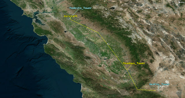
Flight Route and Control Tower Locations
Modeling a control tower transmitter
To keep things easy, each tower is set at an altitude 100 feet above the terrain's surface. You can place them at their actual height if you have that information. Each tower will transmit on a different frequency. Start with the General William J. Fox Airfield's transmitter.
Inserting a Transmitter object
Attach a transmitter object to the General William J. Fox Airfield's tower.
- Select Transmitter (
 ) in the Insert STK Objects tool.
 - Select the Insert Default () method.
- Click .
- Select GenFox_Tower () in the Select Object dialog box.
- Click to accept your selection and to close the Select Object dialog box.
- Right-click on Transmitter1 () in the Object Browser.
- Select Rename.
- Rename Transmitter1 () to GenFox_Tx.
Selecting the transmitter model
Use a Complex Transmitter model.
- Open GenFox_Tx's () Properties ().
- Select the Basic - Definition page when the Properties Browser opens.
- Click the Transmitter Model Component Selector ().
- Select Complex Transmitter Model () in the Transmitter Models list when the Select Component dialog box opens.
- Click to accept your selection and to close the Select Component dialog box.
- Select the Model Specs tab.
- Enter the following specifications:
- Click to accept your changes and to keep the Properties Browser open.
| Option | Value |
|---|---|
| Frequency | 118.525 MHz |
| Power | 25 W |
| Data Rate | 1 Mb/sec |
Configuring the transmitter antenna
Use a dipole antenna that can transmit and receive in a frequency range of 118.000 - 128.000 MHz.
- Select the Antenna tab.
- Select the Model Specs sub-tab.
- Click the Antenna Model Component Selector ().
- Select Dipole () in the Antenna Models list.
- Click to accept your selection and to close the Select Component dialog box.
- Enter the following specifications:
- Click .
| Option | Value |
|---|---|
| Design Frequency | 123 MHz |
| Length | 3.8 ft |
| Efficiency | 80 % |
Constraining the transmitter for TIREM
Disable Line-of-sight, Terrain Mask, or Az-El Mask constraints to take advantage of the over-the-horizon analysis capabilities of the TIREM.
- Select the Constraints - Active page.
- Clear the Enable check box for the Constraint Name Line Of Sight in the Active Constraints list.
- Click to accept your changes and to close the Properties Browser.
Reusing the transmitter for other control towers
All the transmitters are similar except for the frequencies being used by air traffic controllers at the various airfields.
Copying the Transmitter object
The transmitter you attached to the General William J. Fox Airfield's is a good start. Copy the transmitter to reuse on the other towers and modify the copies' individual frequencies.
- Right-click on GenFox_Tx in () the Object Browser.
- Select Copy (
 ).
). - Right-click on Meadows_Tower ().
- Select Paste (
 ).
). - Right-click On Modesto_Tower ().
- Select Paste ().
- Rename the Transmitter () object attached to Meadows_Tower () to Meadows_Tx.
- Rename the Transmitter () object attached to Modesto_Tower () to Modesto_Tx.
Updating the frequency of Meadows Field Airport
Each tower uses a frequency in the VHF range. Start by adding the frequency used by Meadows Field Airport.
- Open Meadows_Tx's () Properties ().
- Select the Basic - Definition page.
- Select the Model Specs tab.
- Enter 118.1 MHz in the Frequency field.
- Click .
Updating the frequency of Modesto City-County Airport-Harry Sham Field
Add the VHF frequency used by the tower at Modesto City-County Airport.
- Open Modesto_Tx's () Properties ().
- Select the Basic - Definition page.
- Select the Model Specs tab.
- Enter 125.3 MHz in the Frequency field.
- Click .
Inserting an aircraft receiver
Many aircraft use a blade antenna designed for a specific frequency range. However, smaller privately owned aircraft often use a dipole antenna. To keep things simple, use a dipole antenna for your analysis.
Inserting a Receiver object
Add a receiver object to the aricraft.
- Insert a Receiver (
 ) object using the Insert Default () method.
 - Select Aircraft () in the Select Object dialog box.
- Click to close the Select Object dialog box.
- Rename Receiver1 () to Aircraft_Rx.
Selecting the receiver model
Use a Complex Receiver model.
- Open Aircraft_Rx's () Properties ().
- Select the Basic - Definition page.
- Click the Receiver Model Component Selector ().
- Select Complex Receiver Model () in the Receiver Models list.
- Click to close the Select Component dialog box.
Configuring the receiver antenna
Use a dipole antenna that can transmit and receive in a frequency range of 118.000 - 128.000 MHz.
- Select the Antenna tab.
- Select the Model Specs sub-tab.
- Click the Antenna Model Component Selector ().
- Select Dipole () in the Antenna Models list.
- Click to close the Select Component dialog box.
- Enter the following specifications:
- Click .
| Option | Value |
|---|---|
| Design Frequency | 123 MHz |
| Length | 3.8 ft |
| Efficiency | 80 % |
Constraining the receiver for TIREM
Disable Line-of-sight, Terrain Mask, and Az-El Mask constraints to take advantage of the over-the-horizon analysis capabilities of the TIREM.
- Select the Constraints - Active page.
- Clear the Enable check box for the Constraint Name Line Of Sight in the Active Constraints list.
- Click to accept your changes and to close the Properties Browser.
Creating an access report
Create an access between the aircraft's receiver the and airfield towers' receivers.
- Right-click on Aircraft_Rx () in the Object Browser.
- Select Access... (
 ) in the shortcut menu.
 - Wait for the Access tool to open.
- Expand (
 ) the following objects in the Associated Objects list:
 - GenFox_Tower ()
- Meadows_Tower ()
- Modesto_Tower ()
- Select the following objects:
- GenFox_Tx ()
- Meadows_Tx ()
- Modesto_Tx ()
- Click
 .
. - Click
Analyzing your link budget
The Detailed Link Budget report will provide you with all the information you need for your analysis. You want to create a custom report that will show specific information concerning your analysis. You want to focus on time, atmospheric absorption and carrier to noise (C/N) ratio. You want to know what time you can expect communications with each tower, how terrain is affecting your communications and you require a C/N of 20 dB or better.
Creating a new report style
Begin creating a custom report for your analysis with a new report style.
- Wait for the Report & Graph Manager to open.
- Select the My Styles (
 ) folder in the Styles panel.
 - Click Create new report style (
 ) in the Styles tool bar.
 - Rename the report to TIREM and CN.
- Select Enter on your keyboard or open the report's Properties ().
Selecting data providers
Select the data provider and elements needed for your analysis.
- Select the Content page.
- Expand () Link Information (
 ) in the Data Providers list.
 - Double-click on the following elements in the order shown to move them from the Data Providers list to the Report Contents list:
- Time (
 )
) - Atmos Loss ()
- C/N ()
- Click .
Generating your report
You can generate individual reports for each airfield or generate one report showing all three airfields. Generate a single report on all three airfields simultaneously.
- Select all three accesses in the Object Type list.
- Select the TIREM and CN report in the My Styles () folder.
- Click .
- Scroll down through the report.
- Keep the report open.
There is a correlation between atmospheric absorption losses (TIREM) and your C/N ratios. The higher the Atmos Loss, the lower the C/N.
Using communication constraints in your analysis
You can constrain your report to show only those times that the C/N is above 20 dB.
- Open Aircraft_Rx's () Properties ().
- Select the Constraints - Active page.
- Click Add new constraints (
 ) in the Active Constraints toolbar.
 - Select C/N in the Constraint Name list when the Select Constraints to Add dialog box opens.
- Click .
- Click to close the Select Constraints to Add dialog box.
- Select the Min check box in the C/N panel.
- Enter 20 dB in the Min field.
- Click to accept your changes and to close the Properties Browser.
Updating your report
Refresh the report to view changes when the C/N constraint is applied.
- Return to the TIREM and CN report.
- Click Refresh (F5) (
 ) in the report toolbar.
 - Scroll down through the report.
There are numerous breaks in your communications due to fluctuations in your C/N values. Most of them are due to terrain but some are a combination of terrain and distance. Communications with General William J. Fox Airfield is very intermittent. Once your aircraft is past the mountain and into the valley near the airport, communications are very good.
You would be looking for solid blocks of communications void of multiple breaks to determine when you can expect unbroken communications with the control towers along your flight route.
Saving your work
Clean up your workspace and save your scenario.
- Close any open reports, properties and tools.
- Save () your work.
Summary
You used the STK TIREM capability to determine communications between an aircraft and three different control towers. Some of the communications were over fairly flat terrain and others were in mountainous terrain. TIREM is perfect for any communications between objects that are below 30 kilometers in altitude and in areas where you have local analytical terrain files available.