3D Graphics - View Position and Direction
![]() ) button on the 3D Graphics toolbar opens the View From/To window, where you can set the view in the active 3D Graphics window.
) button on the 3D Graphics toolbar opens the View From/To window, where you can set the view in the active 3D Graphics window.
You can also select to change the view of the 3D Graphics window by using the View From/To drop down menu. In this drop-down menu, you will find all the top-level objects in the scenario, central bodies, and an option to bring up the View From/To tool.
The View From/To drop-down option is not available for most non-normal 3D windows (obscuration, solar, azel, area), but it is available for the attitude view. For the attitude view window, the only valid object to View From/To is the owner of the window for which the attitude view is being displayed. For this case, there will be only two menu items, the name of the instance that the window was popped up for and the option to bring up the tool.
To set the view in the active 3D Graphics window:
- Select one of the following viewing modes:
- Select an object from the From Position list. The selected object defines the view from position. To add a reference point select the object in the From Position area and click the Add Point button
 . The Select Point window will open.
If you select Latitude, Longitude, Altitude, you can set the coordinate values by clicking the Advanced... button to open the Advanced From/To Options window.
The Latitude, Longitude, Altitude setting displays the Earth altitude in either the MSL or WGS84 shape, based on the setting of the scenario global attribute property Surface Reference of Earth Globes. All other central bodies display their altitude based on their ellipsoid, which is similar to WGS84.
To view from and to an MTO object, its Track ID must be specified in the Computation Track Id field on the MTO Basic Tracks properties page.
- Select an object or reference point from the To Position list, or a direction vector, depending on the viewing mode selected.
- Select the Reference Frame within which the virtual camera will be fixed. Click the Add... button to access the Select Coordinate Axes window, where you can add axes to be used as the reference frame. The reference frame is the coordinate system in which all offsets from the View to/from objects will be stored. When working in Untethered Mode, the Add... button will launch the Select Coordinate System window, which functions the same as the Select Coordinate Axes window but presents you with different reference components - applicable to working in that mode.
- Set any additional viewing options, as needed.
Viewing Modes
From Position to Position
Using the Position to Position viewing mode, you can set the view to one of the following viewing modes. Each view has a specific view from position, view to direction, and view reference point, as illustrated in the following diagram.
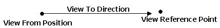
| Viewing Mode | View From Position | View Reference Point | View To Direction |
|---|---|---|---|
| From an object to another object | The object that you are looking from | The object you are looking at | A straight line between the object you are looking from and the object you are looking at. |
| From an object to itself | A software-specified, fixed offset from the object | The object | A straight line between object offset and the object. |
| Along an axes or vector | The object to which the axis or vector belongs | A software-specified, fixed point in space along the axis or vector | A straight line between the view from position and the view reference point. Viewing inward along an axis or vector will reverse the 'view from' position and the 'view reference point'. |
| On a specific latitude and longitude | A software-specified, fixed offset from the specified lat/lon | The specified lat/lon | A straight line between the view from position and the view reference point. |
| On a specific terrain or imagery file | A software-specified offset from the center latitude and longitude of the specified file so that the entire terrain or imagery will be in view. | The center latitude and longitude of the specified file | A straight line between the view from position and the view reference point. |
Along a Direction
Using the Along a Direction viewing mode, you can set the view along an existing vector or a vector created in the Vector Geometry Tool.
In the Direction area select the Add Vector button (![]() ) to open the Select Vector window. The Select Vector window presents a list of available vectors organized hierarchically by central bodies and scenario objects. You can expand or contract the tree by clicking the plus or minus buttons, respectively. Hover over a component to display a tool tip listing component properties. To select a vector, highlight it and click OK. To dismiss the window without selecting a component, click Cancel. Click the Create New Vector button (
) to open the Select Vector window. The Select Vector window presents a list of available vectors organized hierarchically by central bodies and scenario objects. You can expand or contract the tree by clicking the plus or minus buttons, respectively. Hover over a component to display a tool tip listing component properties. To select a vector, highlight it and click OK. To dismiss the window without selecting a component, click Cancel. Click the Create New Vector button (![]() ) to open the Add Geometry Component window and create a custom vector.
) to open the Add Geometry Component window and create a custom vector.
Selected by default, the Outward option maintains the 'view from' and 'view direction' position. Selecting the Inward option will reverse the 'view from' position and the 'view direction'.
Untethered
Selecting Untethered enables you to move freely in space using the keyboard. When you select this mode, the view is not constrained along any vector or pointed towards any object. The initial view is set using the selected object, but you are not attached to these objects thereafter. With the keyboard, you can move freely about the scene using the keys listed in the table below. The directional keys can be used in combination to perform combined movements.
The untethered mode supports any coordinate system. For example, if "Aircraft1 Body" is selected as the coordinate system, the camera's position and orientation are stored in terms of that system. Therefore, if the scene is animated, the camera stays fixed in respect to the system.
The functions of the keyboard keys in untethered mode follow.
| Key | Function |
|---|---|
| q | Set the rate of movement slower by one half the current rate. |
| e | Set the rate of movement faster by twice the current rate. |
| w | Move in. |
| s | Move out. |
| a | Move left. |
| d | Move right. |
| z | Move down. |
| c | Move up. |
You can also use the mouse in untethered mode to:
- Change your view direction. The default rate of movement is one meter per second, which you can adjust using the keys as well.
- Move forward or backward as if you were zooming. To pan left, right, up, or down, press shift and move the mouse.
Additional Viewing Options
The View/From To window provides the following additional options:
Constrained "Up" Vector. If selected, indicate which axis of the selected reference frame should be fixed pointing vertical in the 3D window. You can also apply additional rotation constraints using keyboard controls while in Constrained "Up" Vector mode.
Allow Rotation Over "Up". If this option and Constrained "Up" Vector are selected, the camera can rotate over the top of the "up" vector.
Unconstrained Rotation. Enables you to move the view in any direction without constraints. You can apply rotation constraints using the keyboard while in unconstrained rotation mode. Click Advanced... to set the keyboard constraints to rotate about the reference axes or the screen axes.
Show "Track Ball". When using a virtual track ball, the left mouse button enables you to rotate freely about the viewed object when in the center of the window. Towards the edges of the scene, using the left mouse button will twist the view around the viewed object. If this option and the Unconstrained Rotation option are selected, the boundary of these two regions is shown.
Lock in View Direction. Disables all rotation in the scene. Zooming is still possible, as is twisting - if Constrained "Up" Vector is not selected.
Fixed Distance. If selected, zooming is disabled. You must specify the distance of the view, and whether the distance is defined as the distance from the 'view reference point' or to it (from the 'view from' position).
Use Camera Inertia. Enables you to quickly rotate, pan, or zoom to a location before using more precise mouse input.
Advanced button. Click to access the Advanced From/To Options window.
Reset View button. Click to reset the 3D Graphics window view to the view currently selected in the View From/To window.