STK natively supports the loading of glTF models (*.gltf, *.glb) that adhere to the glTF 2.0 specification. These models allow STK to make use of a system known as Physically Based Rendering (PBR), which produces a high level of visual realism. This system allows model artists to specify physical properties of materials, such as whether a given surface is metallic, and the level of roughness. A PBR shader, customized for the STK rendering environment, calculates accurate lighting conditions on these physically based materials.
STK supports glTF files in the plain-text .gltf format, both with and without embedded binary resources. It also supports glTF binary (.glb) files, which typically embed their resources, such as texture images. Both forms may contain STK-specific metadata, such as attach points and articulations.
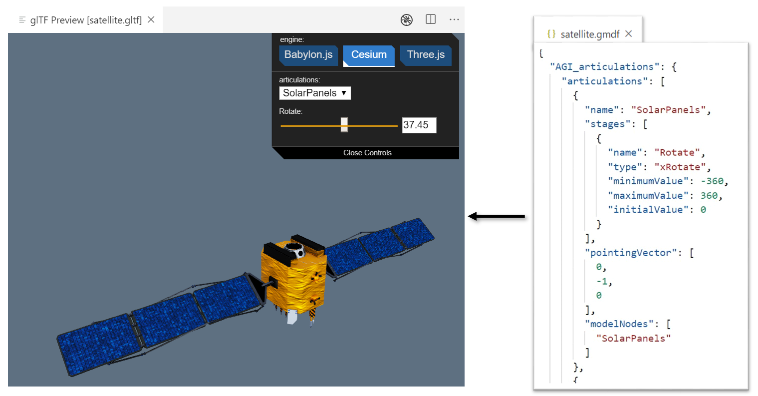
STK augments the glTF format through the use of a separate metadata file that defines attach points for sensors and vapor trails, range and makeup of articulated appendages, the pointing of components at objects in the scenario, and the makeup of solar panel groups. This glTF MetaData file (.gmdf) sits next to the .gltf file and loads automatically when the base glTF model loads. GMDF files are unique to STK and are entirely optional. Below is an example.
The specification for glTF metadata files is maintained on GitHub. At the top of that page are links to the two glTF extensions, if you wish to embed this data into glTF directly. Further down is a hypothetical example GMDF file.
The GMDF repository also has a folder called "samples" with working sample models, their GMDF and embedded equivalents, and some screen shots. The models themselves are minimal examples, but all of the different types of STK metadata include working examples. The GMDF file for VehicleTest.gltf is here.
Creating articulations in a glTF model
To author articulations for a glTF model, you need to annotate the gmdf file to identify glTF nodes eligible for articulation as well as the constraints on the node articulation (minimum value, maximum value, and default value). A gmdf file follows a json schema for annotating STK-specific metadata on a glTF model. When loading a glTF model, STK looks for a gmdf file with the same base name as the glTF file, for example C:\Models\satellite.gltf and C:\Models\satellite.gmdf).
The root of the json object defines two properties, “AGI_articulations” and “AGI_stk_metadata” for STK-specific annotations. The “AGI_articulations” property defines two child properties: “articulations” and “attachPoints.”
{
    "AGI_articulations": {
        "articulations": [...]
    },
    "AGI_stk_metadata": {
        ...
    }
}
The articulations property is a list of json-formatted blocks, where each json block defines a named articulation. Each articulation in the list must define the following properties:
| Articulation Property | Description |
|---|---|
| name | This is the name of the articulation that STK uses to identify this articulation. |
| modelNodes | This is a list of glTF nodes that this articulation will affect. You can list multiple nodes to apply the articulation to all nodes at the same time — just like rotating all four car tires at the same time. |
| stages |
This is a list of all possible articulations for the modelNodes. Stage definition includes:
|
Alternatively, you can define gltf articulations and solar panel markup by manually editing a glTF model to include the AGI_articulations or AGI_stk_metadata glTF Vendor extensions. This is often the preference for the final publication of a glTF model that is not expected to receive any further updates from the content creators, and it allows for all of the STK-specific annotations to be embedded inside the model file.
Configuring model pointing for a glTF model articulation
To enable model pointing, a glTF node must define an articulation in the gmdf file that defines xRotate, yRotate, or zRotate for enabling rotation articulations. Inside this articulation definition, you can define the “pointingVector” property to enable model pointing within these articulation constraints.
       "articulations": [

		    {
                "name": "Root",
                "modelNodes": [
                    "root"
                ],
                "pointingVector" : [
                    0.0,
                    1.0,
                    0.0
                ],
                "stages": [
                    {
                        "name": "Roll",
                        "type": "xRotate",
                        "minimumValue": -360.0,
                        "maximumValue": 360.0,
                        "initialValue": 0.0
                    },
                    ...
The "pointingVector" property describes a direction in which pointing will occur. This vector is in the node's local coordinates within the model. Note that +Y is up, per the glTF specification. For example, if a satellite model has the surface of the solar panels pointing UP on the model, the pointing vector for these panels should have the configuration [0, 1, 0] to indicate that the solar cells should be facing the pointing target defined in STK.
Configuring attach points for a glTF model
Many features in STK interact with models through attach points, such as sensor placement or vapor trails. To define attach points for glTF models, define the "attachPoints" property to assign a uniquely identifiable name to a glTF node. The attachPoints property defines a list of glTF node names that are available as model attach points.
{
    "AGI_articulations": {
        "attachPoints": ["LeftPodAttachment", "RightPodAttachment"]
    }
}
Using animations with glTF 3D models
When a glTF 3D model contains an animation, the name of that animation appears as an STK articulation with two transformations: "Enable" and "Seconds."
The range for Enable is 0.0 to 1.0 and indicates whether this particular animation exerts influence over the model or not. A value of zero (0.0) disables the animation, while one (1.0) enables the animation. You should avoid intermediate values except for very brief transitions.
The range for Seconds begins at 0.0 and ends with the length of the glTF animation as measured in seconds. This allows you to control the playback of the glTF animation.
Example
- Create an Aircraft (
 ) object in STK.
 - Create a route for the aircraft.
- Right-click on Aircraft () in the Object Browser.
- Open the Aircraft's () properties (
 ).
). - Select the 3D Graphics - Model page.
- Load the c-130_hercules.glb model.
- Click .
- Click button in the Articulations field.
- Select the LandingGear articulation.
- Set the value for Enable to 1.0. There is no visible change when you enable this animation.
- Select the Seconds option.
- Slowly move the value while watching the underside of the 3D model. The landing gear executes a sequence of steps needed to retract.
Configuring solar panel groups
All mesh geometry contained in nodes assigned to a Solar Panel Group is considered to be the surface of light-receiving material. The back, sides, and other supporting structures should be in separate node(s) from the actual solar cells. Multiple glTF nodes can belong to a single group of solar panels. This allows the STK Solar Power Tool to analyze which portions of a model are exposed to light and are generating power. Each group has an efficiency rating, as a percentage from 0.0 to 100.0, that indicates how efficiently the solar cells convert solar to electrical energy.
This example shows a solar panel group at 14% power efficiency:
{
    "AGI_stk_metadata": {
        "solarPanelGroups": [
            {
                "name": "Geo1",
                "modelNodes": [
                    "SolarPanel"
                ],
                "efficiency": 14.0
            }
        ]
    }
}
Configuring no-obscuration nodes
Mesh geometry contained in "no-obscuration" nodes do not affect the calculations of STK's Sensor Obscuration Tool. The geometry of such marked nodes are invisible to the sensors for the purpose of this calculation, as if the sensor is able to see through it unobscured.
{
    "AGI_stk_metadata": {
        "noObscurationNodes": [
            "Node1"
        ]
    }
}
Defining a reflection environment for glTF models
In Physically Based Rendering (PBR), one of the most important elements to contribute to the realism of a material is the reflection environment. In addition to providing a visual context of the surrounding environment, the reflection environment contributes to the lighting of the model. This technique is known as image-based lighting.
In STK, there are two mechanisms for reflection environments: static High Dynamic Range (HDR) image, and a procedurally generated environment. If you do not use HDR-based reflection environments, STK will default to the procedurally generated environment.
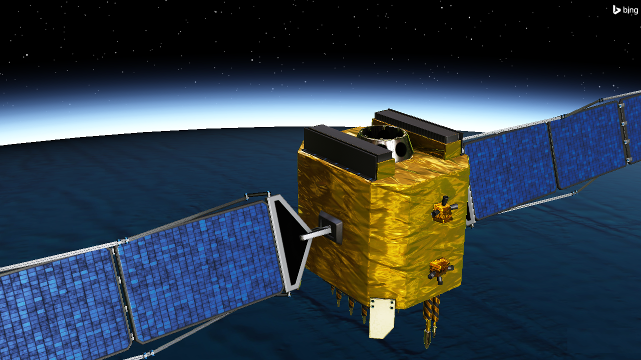
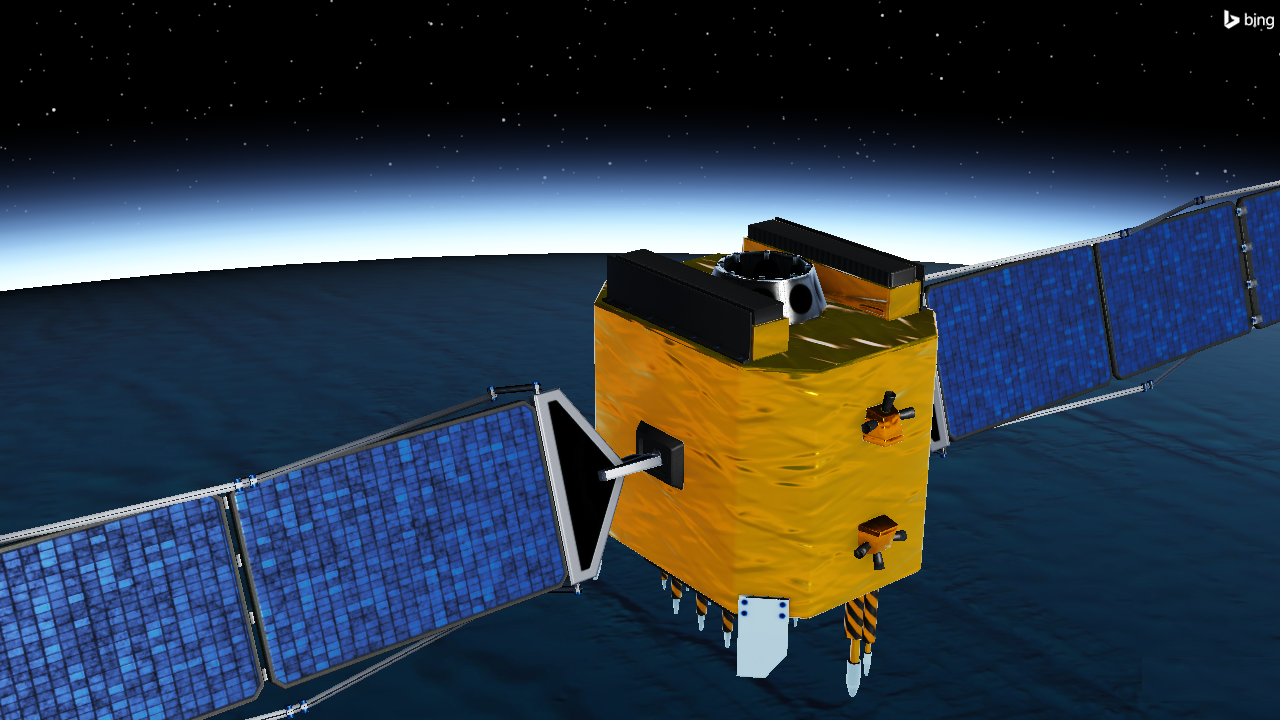
satellite.gltf with an HDR static reflection environment (Top) and STK’s procedurally generated reflection environment (Bottom)
In the case of the procedurally generated environment, STK reflections into the environment uses the model’s current altitude to render a transition between a blue atmosphere, when close to the ground, and deep space, as the model exits the central body’s atmosphere.
Alternatively, you can define specific environments for glTF models in the HDR format, a common standard format for encoding light conditions with far more precision. While it is possible to capture our own HDR panoramic scenes for use in STK, many sites publish high-quality HDR images that are sufficient approximations for a local environment in STK (e.g., https://hdrihaven.com/). In most cases, the details of the reflected environment are less important than the lighting variations rendered in the model that show off characteristics that you expect, such as blue sky above and ground below.
The static reflection map is not actually part of a glTF model. It is an external image file specified through the Model Properties page, shown below.
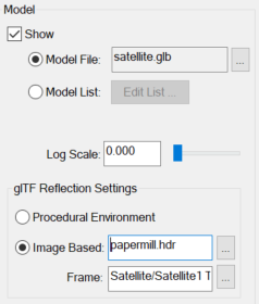
STK provides a Connect command to define a reflection environment for a given glTF model. This command requires two key pieces of information to properly define the reflection environment: the filepath to an HDR image defining the reflection environment, and a ReferenceFrame for the HDR reflection environment. The reference frame property defines how to orient the reflection map in the world and is in the format: “<TruncatedObjPath> <SystemName>”.
For ground based models, it is common to assign a TopoCentric reference frame to the reflection map, which ensures that the reflection environment is always oriented up regardless of the rotation applied to the model. For example, you can define the reflection map shown on the satellite image above in the facility’s topocentric frame with the following connect command:
VO */Facility/Facility1 ModelReflectionEnvironment FilePath "environment.hdr" ReferenceFrame "Facility/Facility1 TopoCentric"
For celestial-based reflection maps (star maps), it is recommended that the Inertial System of the scene’s Central Body is used:
VO */Satellite/Satellite1 ModelReflectionEnvironment FilePath "environment_starmap.hdr" ReferenceFrame "CentralBody/Earth Inertial"
glTF extensions supported by STK
STK supports the following glTF extensions:
| Extension | Web Reference |
|---|---|
| KHR_materials_pbrSpecularGlossiness | https://github.com/KhronosGroup/glTF/tree/main/extensions/2.0/Archived/KHR_materials_pbrSpecularGlossiness |
| KHR_materials_unlit | https://github.com/KhronosGroup/glTF/tree/main/extensions/2.0/Khronos/KHR_materials_unlit |
| KHR_draco_mesh_compression | https://github.com/KhronosGroup/glTF/tree/main/extensions/2.0/Khronos/KHR_draco_mesh_compression |
| KHR_materials_clearcoat | https://github.com/KhronosGroup/glTF/tree/main/extensions/2.0/Khronos/KHR_materials_clearcoat |
| KHR_mesh_quantization | https://github.com/KhronosGroup/glTF/tree/main/extensions/2.0/Khronos/KHR_mesh_quantization |
| KHR_texture_transform | https://github.com/KhronosGroup/glTF/tree/main/extensions/2.0/Khronos/KHR_texture_transform |
| KHR_texture_basisu | https://github.com/KhronosGroup/glTF/tree/main/extensions/2.0/Khronos/KHR_texture_basisu |
| EXT_texture_webp | https://github.com/KhronosGroup/glTF/tree/main/extensions/2.0/Vendor/EXT_texture_webp |
| EXT_mesh_gpu_instancing | https://github.com/KhronosGroup/glTF/tree/main/extensions/2.0/Vendor/EXT_mesh_gpu_instancing |
| EXT_meshopt_compression | https://github.com/KhronosGroup/glTF/tree/main/extensions/2.0/Vendor/EXT_meshopt_compression |
| AGI_articulations | https://github.com/KhronosGroup/glTF/tree/main/extensions/2.0/Vendor/AGI_articulations |
| AGI_stk_metadata | https://github.com/KhronosGroup/glTF/tree/main/extensions/2.0/Vendor/AGI_stk_metadata |