3D Graphics Properties for Satellites - Pass
Use to control the display of satellite orbits in the 3D Graphics window.
Leading/Trailing
Inherit From 2D Graphics. If selected, options set in the 2D Pass Graphics are used to display the satellite's pass in the 3D Graphics window, and the Lead and Trail Type options are disabled. If not selected, orbit display parameters specified here are used.
Ground Track or Orbit Track
The display of leading and trailing portions of a route, ground track, trajectory, or orbit is based on the vehicle's current position.
Lead Type. Defines the display of the leading portion of a vehicle tracks. (The leading portion of a vehicle's track begins at the vehicle's present position and moves forward half the span of its ephemeris.)
Trail Type. Defines the display of the trailing portion of vehicle's track. (The trailing portion of a track begins at the vehicle's present position and moves backward half the span of the vehicle's ephemeris.)
Values for Lead Type or Trail Type are:
- One Pass. (Satellites only) Displays forward to the first pass break. At the pass break, display forward to the next one.
- Time. Specifies the amount of time (in seconds) that the leading or trailing portion is displayed.
- Percent. Indicates the percentage of the leading portion or trailing portion that is displayed.
- Quarter. Displays one quarter of the leading or trailing portion.
- Half. Displays one half of the leading or trailing portion.
- Full. Displays the entire leading or trailing portion.
- All. Displays the track spanning the entire vehicle ephemeris.
- None. Does not display the leading or trailing portion.
- Current Interval. When the vehicle is using Access Intervals, Custom Intervals or Realtime Intervals, display the leading portion of the vehicle's track for the graphics interval that contains the current animation time. When using Basic graphics options the entire leading portion will be displayed.
- Same As Lead option. Uses the Lead Type value for Trail Type.
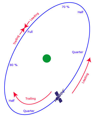
Bear in mind that Lead and Trail Type options with names such as Quarter, Half, Full and Percent are defined with reference to the leading or trailing portion only. For example, as illustrated in the following diagram, a Lead Type of Half for an Orbit Track displays one quarter of the orbit track forward from the current position of the satellite:
The following 3D Graphics image shows a satellite for which Lead Type = Quarter and Trail Type = Half.
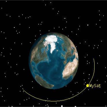
To see the trailing portion of the orbit track, you must animate forward until the satellite reaches or passes the point that is required by the selected Trail Type. In the above example, it is necessary to animate through one quarter of the orbit, since the Trail Type is defined as Half.
Tick Marks
Defines the display of tick marks representing milestones at specified intervals along a vehicle's ground and/or orbit track in the 3D Graphics window.
Ground Track or Orbit Track
Show. Displays tick marks> and enables you to modify the following attributes.
Marker Type. Displays as either a line or point.
Point Size. The size of the point representing each tick mark.
Line Width. The width of the line representing each tick mark.
Tick Width. Indicates the actual distance that the tick extends across the ground track or orbit.
Tick Style. Draws the tick marks in a radial or cross-track direction for an orbit track.
Time Between Marks. Indicates the time elapsed between each milestone indicated by a tick mark along the vehicle's path. This value applies to all tick marks showing in the 3D Graphics window.