Sensor Types
Angular rate sensors
You can use angular rate sensors instead of an IMU as the primary feedback mechanism for the Attitude Control System. The most common configuration of angular rate sensors is to place one sensor aligned with each of the axes [X,Y,Z] of the spacecraft frame.
Valid angular rate sensor configurations
SOLIS supports single sensor configurations. The rate feedback values on the two remaining orthogonal axes are assumed to be zero.
SOLIS also supports dual sensor configurations as long as the measurement axes are not parallel. The rate feedback values on the remaining orthogonal axis are assumed to be zero.
SOLIS supports configurations of three or more sensors as long as they do not all have their measurement axes in the same plane. Redundant sensors are provided equal weight.
Angular rate sensors glossary
| Spacecraft Configuration Parameters | Description | Units |
|---|---|---|
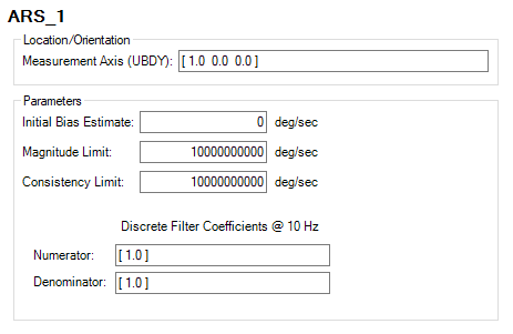
| Measurement Axis (UBDY) | This is a unit vector defining the axis about which rotation is sensed. | N/A |
| Initial Bias Estimate | This is the estimated value of the sensors bias used to compensate for known biases. | deg/s |
| Magnitude Limit | Sensor measurements are marked invalid if their magnitude is above this value. | deg/s |
| Consistency Limit | This is the maximum change in angular velocity allowed per cycle. Spacecraft holds last value until a valid measurement exists. | deg/s |
| Discrete Filter | Defines order of rate sensor processing filter (typically a unity-gain low-pass filter). | N/A |
| ODySSy Simulation Parameters | Description | Units |
|---|---|---|
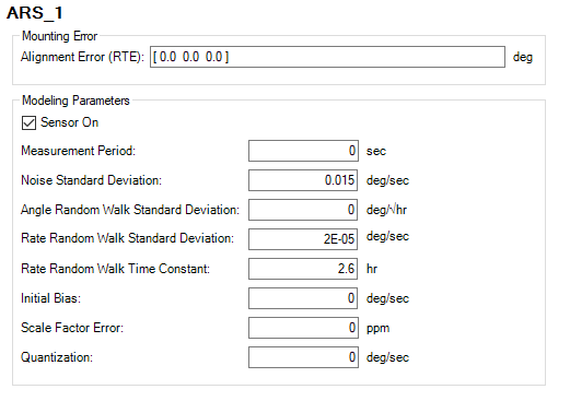
| Alignment Error (RTE) | These are rotation angles from FSW measurement axis to true sensor orientation. | deg |
| Sensor On | Sets the hardware "on" state, which is useful for failure analysis. | N/A |
| Measurement Period | Defines the rate at which the sensor updates measurements. | s |
| Noise Standard Deviation | Specifies the magnitude of injected white noise on a given sensor. | deg/s |
| Angle Random Walk Standard Deviation | "... the average deviation or error that will occur when you integrate the signal. This is error occurring specifically because of noise in the rate signal, independent of other characteristics that contribute to angle error. This error will increase the longer you integrate, and provides a fundamental limitation to any angle measurement that relies solely on integration of rate." From Angle Random Walk by Dr. Walter Stockwell, Crossbow Technology, Inc. | deg/√hr |
| Rate Random Walk Standard Deviation | Represents the 1-sigma drift of the bias over the time frame specified (Rate Random Walk Time Constant). Unlike Angle Random Walk, it directly affects the modeled bias of the rate sensor. | deg/s |
| Rate Random Walk Time Constant | Specifies the time it takes to for the rate to drift by the Rate Random Walk. | hr |
| Initial Bias | Specifies the bias in sensor measurement relative to true motion. | deg/s |
| Scale Factor Error | Positive results in larger slope of estimate relative to truth. | ppm (parts per million) |
| Quantization | Specifies the measurement resolution of the sensor. Entering "0" indicates no discretization of the true value. | deg/s |
GPS
GPS sensors measure a satellite's position and velocity and are typically used for orbit determination. The associated parameters for GPS processing are available on the Orbit Determination System page.
GPS glossary

| Parameter/Control | Description | Units |
|---|---|---|
| Sensor On | Select this to "turn on" the GPS receiver. | bool |
| Measurement Period | Selects how frequently STK position and velocity estimates are passed to the spacecraft's on-board fixed gain orbit filter. | s |
| Position Bias (LVLH) | Specifies a position bias to be added to the STK spacecraft position measurement before it is passed to the fixed gain orbit filter. The coordinate frame of the bias is Local Vertical, Local Horizontal (LVLH). | m |
| Position Noise Standard Deviation (LVLH) | Specifies the standard deviation of noise to be added to the STK spacecraft position measurement before it is passed to the on-board fixed gain orbit filter. The coordinate frame of position noise is Local Vertical, Local Horizontal (LVLH). | m |
| Velocity Bias (LVLH) | Specifies a velocity bias to be added to the STK spacecraft velocity measurement before it is passed to the on-board fixed gain orbit filter. The coordinate frame of the bias is Local Vertical, Local Horizontal (LVLH). | m/s |
| Velocity Noise Standard Deviation (LVLH) | Specifies the standard deviation of noise to be added to the spacecraft velocity measurement before it is passed to the on-board fixed gain orbit filter. The coordinate frame of velocity noise is Local Vertical, Local Horizontal (LVLH). | m/s |
Horizon sensor pairs
Horizon sensors provide angular measurements to the earth's horizon from the sensor boresight about an orthogonal measurement axis. These sensors are typically used in nadir pointing applications. SOLIS supports two horizon sensors that are offset from a configurable body frame vector in order to place the horizon in the field of view when the configurable vector is aligned with nadir. The two horizon angle measurements are used to estimate the nadir vector for attitude determination.
Horizon sensor pairs glossary
| Spacecraft Configuration Parameters | Description | Units |
|---|---|---|
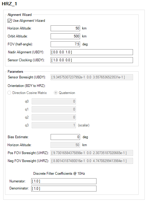
| Use Alignment Wizard | Automatically generate horizon sensor pos/neg FOV boresight vectors and orientation based on horizon altitude, orbit altitude, field of view, nadir alignment, and sensor clocking vectors. | N/A |
| Horizon Altitude | Specify the estimated altitude above central body mean radius to define as the horizon. | km |
| Orbit Altitude | Specify the average altitude of spacecraft orbit. | km |
| FOV (half-angle) | Specify the half angle defining width of sensor view. | deg |
| Nadir Alignment (UBDY) | Specify the unit vector in the spacecraft frame defining the axis for nadir pointing. | N/A |
| Sensor Clocking (UBDY) | Specify the unit vector in the spacecraft frame defining the axis to clock the sensor pointing frame to. | N/A |
| Sensor Boresight (UBDY) | Defines the HRZ sensor boresight in the spacecraft body frame. | N/A |
| Orientation (BDY to HRZ) | Enables you to define a horizon sensor frame that is different from the spacecraft body frame. Use a direct cosine matrix or quaternion to define the rotation from the body frame to the horizon sensor frame. | DCM/Quaternion |
| Bias Estimate | This is an estimated value of sensor bias used to compensate for known sensor biases. | deg |
| Horizon Altitude | Specify the altitude above central body mean radius to define as the horizon. | km |
| Pos FOV Boresight (HRZ) | Defines the boresight of the positive (space) side of FOV. | N/A |
| Neg FOV Boresight (HRZ) | Defines the boresight of the negative (central body) side of FOV. | N/A |
| Discrete Filters | Specify filter values for the angle measurement. | N/A |
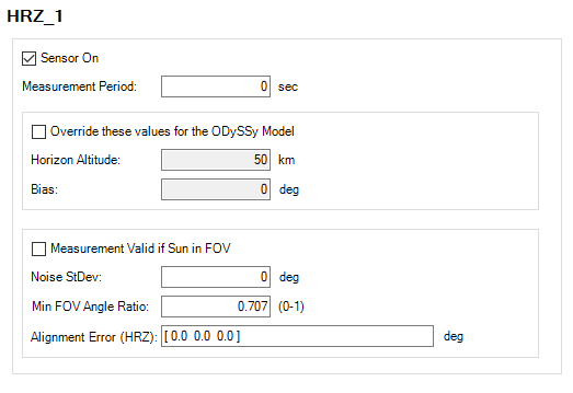
| ODySSy Simulation Parameters | Description | Units |
|---|---|---|
| Sensor On | Sets hardware "on" state, which is useful for failure analysis. | N/A |
| Measurement Period | Defines the rate at which the sensor updates measurements. | s |
| Horizon Altitude | Specify the true altitude above central body mean radius to define as the horizon. | km |
| Bias | Specify the horizon angle bias in sensor frame. | deg |
| Measurement Valid if Sun in FOV | Allows valid measurements if the sun is in the horizon sensor's field of view. | N/A |
| Noise StdDev | Specify the horizon sensor angular noise. | deg |
| Min FOV Angle Ratio | NadirPosFOVAngle - NadirNegFOVAngle > Ratio*FOV must be true for validity. |
0-1 |
| Alignment Error (HRZ) | Specify the rotation angles from FSW measurement axis to true sensor orientation. | deg |
IMUs
IMUs (Inertial Measurement Units) are the primary feedback mechanism for the Attitude Control System. A single IMU can measure both the angular rate and linear acceleration of the spacecraft in all three axes. You can define separate angular rate and acceleration measurement frames. You also have the option to exclude acceleration measurements.
IMU glossary
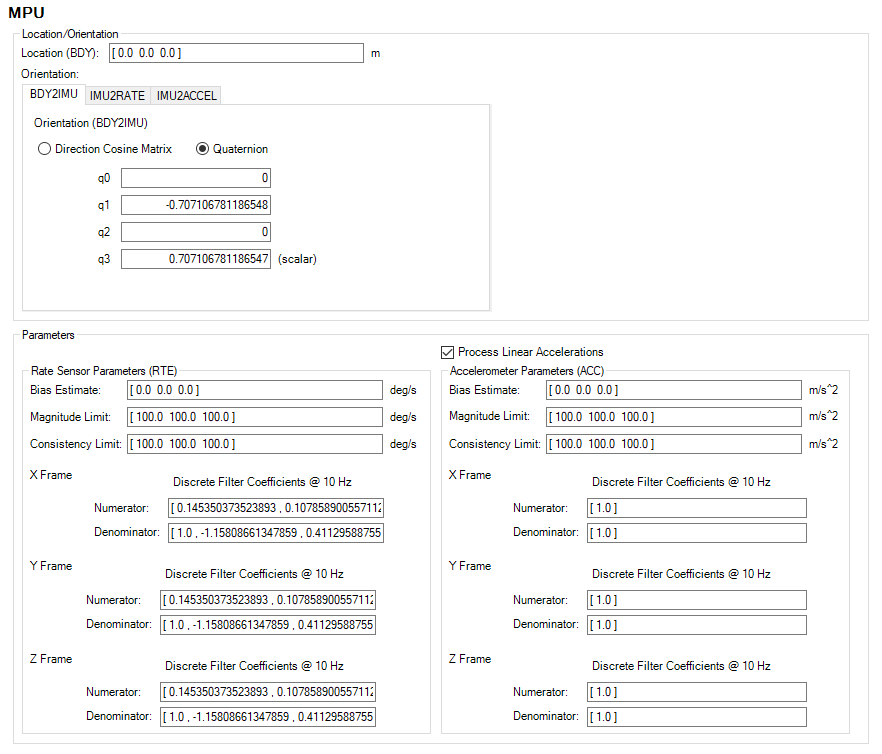
| Spacecraft Configuration Parameters | Description | Units |
|---|---|---|
| Location (BDY) | Specify the location of the IMU in the BDY frame. | m |
| Orientation, BDY2IMU | Specify the rotation quaternion from BDY frame to IMU frame. | N/A |
| Orientation, IMU2RATE | Specufy the rotation quaternion from IMU frame to RATE frame. Enables you to specify a RATE frame separate from the base IMU frame. | N/A |
| Orientation, IMU2ACCEL | Specify the rotation quaternion from IMU frame to ACC frame. Enables you to specify an ACC frame separate from the base IMU frame. | N/A |
| Process Linear Accelerations | Enables/disables linear acceleration component of the IMU. | N/A |
| Bias Estimate (RTE) | Specify the estimate of bias in the angular rate bias in the RTE frame. | deg/s |
| Magnitude Limit (RTE) | Specify the magnitude angular rate limit per axis for fault check. | deg/s |
| Consistency Limit (RTE) | Specify the consistency angular rate limit per axis for fault check. | deg/s |
| Bias Estimate (ACC) | Specify the estimate of bias in the linear acceleration bias in the RTE frame. | deg/s2 |
| Magnitude Limit (ACC) | Specify the magnitude acceleration limit per axis for fault check. | deg/s2 |
| Consistency Limit (ACC) | Specify the consistency acceleration limit per axis for fault check. | deg/s2 |
| Discrete Filter (RTE and ACC X/Y/Z Frame) | Defines the order of angular rate and acceleration processing filter, typically a unity-gain low-pass filter. | N/A |
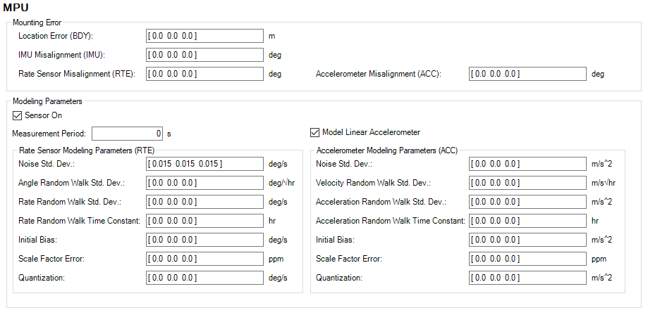
| ODySSy Simulation Parameters | Description | Units |
|---|---|---|
| Location Error (BDY) | Location error of the IMU in the BDY frame | m |
| IMU Misalignment (IMU) | Rotation angles from FSW measurement frame to true sensor orientation | deg |
| Rate Sensor Misalignment (RTE) | Rotation angles from FSW measurement frame to true sensor orientation | deg |
| Accelerometer Misalignment (ACC) | Rotation angles from FSW measurement frame to true sensor orientation | deg |
| Sensor On | Sets hardware "on" state; useful for failure analysis. | N/A |
| Measurement Period | Defines the rate at which the sensor updates measurements. | s |
| Model Linear Accelerometer | Enables/disables linear acceleration component of the IMU. | N/A |
| Noise Std. Dev. (RTE) | Magnitude of injected white noise | deg/s |
| Angle Random Walk Std. Dev. (RTE) | "... the average deviation or error that will occur when you integrate the signal. This is error occurring specifically because of noise in the rate signal, independent of other characteristics that contribute to angle error. This error will increase the longer you integrate, and provides a fundamental limitation to any angle measurement that relies solely on integration of rate." From Angle Random Walk by Dr. Walter Stockwell, Crossbow Technology, Inc. | deg/√hr |
| Rate Random Walk Std. Dev. (RTE) | Represents the 1-sigma drift of the bias over the time-frame specified (Rate Random Walk Time Constant). Unlike Rate Random Walk, it directly affects the modeled bias of the rate. | deg/s |
| Rate Random Walk Constant (RTE) | The time it takes for the rate to drift by the Rate Random Walk | hr |
| Initial Bias (RTE) | Bias in sensor measurement relative to true motion | deg/s |
| Scale Factor Error (RTE) | Positive results in larger slope of estimate relative to truth | ppm |
| Quantization (RTE) | Measurement resolution of the sensor; entering "0" indicates no discretization of the true value | deg/s |
| Noise Std. Dev. (ACC) | Magnitude of injected white noise | m/s2 |
| Velocity Random Walk Std. Dev. (ACC) | "... the average deviation or error that will occur when you integrate the signal. This is error occurring specifically because of noise in the rate signal, independent of other characteristics that contribute to angle error. This error will increase the longer you integrate, and provides a fundamental limitation to any angle measurement that relies solely on integration of rate." From Angle Random Walk by Dr. Walter Stockwell, Crossbow Technology, Inc. | m/s/√hr |
| Acceleration Random Walk Std. Dev. (ACC) | Represents the 1-sigma drift of the bias over the time-frame specified (Acceleration Random Walk Time Constant). Unlike Velocity Random Walk, it directly affects the modeled bias of the acceleration. | m/s2 |
| Acceleration Random Walk Constant (ACC) | The time it takes for the rate to drift by the Acceleration Random Walk | hr |
| Initial Bias (ACC) | Bias in sensor measurement relative to true motion | m/s2 |
| Scale Factor Error (ACC) | Positive results in larger slope of estimate relative to truth. | ppm |
| Quantization (ACC) | Measurement resolution of the sensor; entering "0" indicates no discretization of the true value | m/s2 |
Magnetometers
Magnetometers are often used in Low-Earth-Orbit satellites to provide attitude information relative to the earth's magnetic field. The measured strength and orientation is then used for torque estimation when Magnetic Torque Rods are used for momentum control. Spacecraft without magnetometers generally use a magnetic model to estimate the torque exerted by Magnetic Torque Rods.
Magnetometers glossary
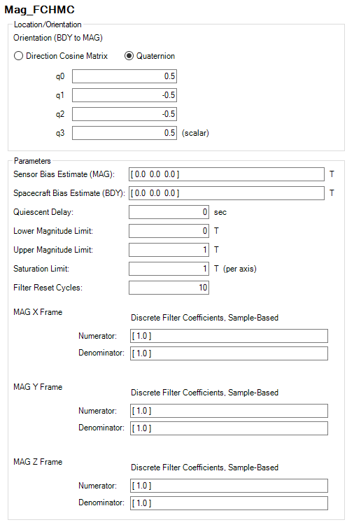
| Spacecraft Configuration Parameters | Description | Units |
|---|---|---|
| Orientation | Three-axis angular orientation of the sensor frame defined as a DCM or quaternions | N/A |
| Sensor Bias Estimate (MAG) | Estimated value of sensor bias used to compensate for known sensor biases | T |
| Spacecraft Bias Estimate (BDY) | Estimated value of bias used to compensate for known spacecraft magnetic field biases | T |
| Quiescent Delay | Time to delay mag measurement validity after torque rods turn off | s |
| Lower/Upper Magnitude Limit | Sensor measurements are marked as invalid if the magnitude is below/above these values. | T |
| Saturation Limit | Maximum magnetic measurement in any axis | T (per axis) |
| Filter Reset Cycles | Number of cycles allowed without a valid sensor measurement before filter resets | N/A |
| Discrete Filter (MAG X/Y/Z Frame) | Defines order of magnetometer processing filter, typically a unity-gain low-pass filter. | N/A |

| ODySSy Simulation Parameters | Description | Units |
|---|---|---|
| Alignment Error (MAG) | Rotation angles from FSW measurement axis to true sensor orientation | deg |
| Sensor On | Sets the hardware "on" state, which is useful for failure analysis. | N/A |
| Measurement Period | Defines the rate at which the sensor updates measurements. | s |
| Spacecraft Bias (BDY) | True spacecraft magnetic field bias in spacecraft frame | T |
| Sensor Bias (MAG) | True magnetic field bias in sensor frame | T |
| Noise Standard Deviation (MAG) | Magnetic field noise in sensor frame | T |
| Scale Factor Error (MAG) | Positive results in larger slope of estimate relative to truth. | ppm |
| Quantization | Measurement resolution of the sensor; entering "0" indicates no discretization of the true value | T |
Star Trackers
Star Trackers provide a three-axis attitude estimate of the vehicle by correlating sensed star patterns to known positions of stars. SOLIS models star trackers using truth attitude and enables you to introduce bias and noise by adjusting parameters.
Star Tracker glossary

| Spacecraft Configuration Parameters | Description | Units |
|---|---|---|
| Boresight | If you select Specify Full Mounting, it defines the boresight relative to the STR orientation. If you select Specify Mount Axis Only (UBDY), it defines the boresight relative to the spacecraft BDY frame. | N/A |
| Orientation | Three-axis angular orientation of the sensor frame defined as a DCM or quaternions; only available if you select Specify Full Mounting. | N/A |
| Propagate Star Tracker Measurement | If you select this check box, SOLIS will enable propagation of the star tracker measurement to the current time. If not, SOLIS will not enable propagation of the star tracker measurement to the current time, and the measurement time is assumed to be current time. | N/A |
| Measurement Bias Time | Bias time delta subtracted from measurement time if propagation enabled. | s |
| Define custom Sensor REF frame | If you select this check box, SOLIS will not perform a default conversion from J2000 to Spacecraft CBI on the measurement, but will employ a user-supplied ECI to Sensor REF transformation instead. | N/A |

| ODySSy Simulation Parameters | Description | Units |
|---|---|---|
| Alignment Error (STR) | Rotation angles from FSW measurement axis to true sensor orientation. | deg |
| Sensor On | Sets hardware "on" state, which is useful for failure analysis. | N/A |
| Measurement Period | Defines the rate at which the sensor updates measurements. | s |
| Measurement Timetag Error | Error on star tracker measurement timetag | s |
| Angular Noise Standard Deviation: About Boresight | Standard deviation of noise offset from specified boresight vector | deg |
| Angular Noise Standard Deviation: Perpendicular To Boresight | Standard deviation of noise offset perpendcular to specified boresight vector | deg |
| Keep Out Angle: Sunlight Keep Out Angle | Sunlight keep-out angle of sensor view | deg |
| Keep Out Angle: Hoirzon Keep Out Angle | Horizon keep-out angle of sensor view | deg |
| Measurement Reference Frame | Reference frame that the sensor produces data in, usually J2000 for star trackers | deg |
| Angular Noise Standard Deviation | Angular noise about the boresight and perpendicular to the boresight | deg |
| Sunlight Keep-Out Angle | Sensor rejects measurements if they are in this angle of the estimated sun vector. | deg |
| Horizon Keep-Out Angle | Sensor rejects measurements if they are in this angle of the estimated horizon. | deg |
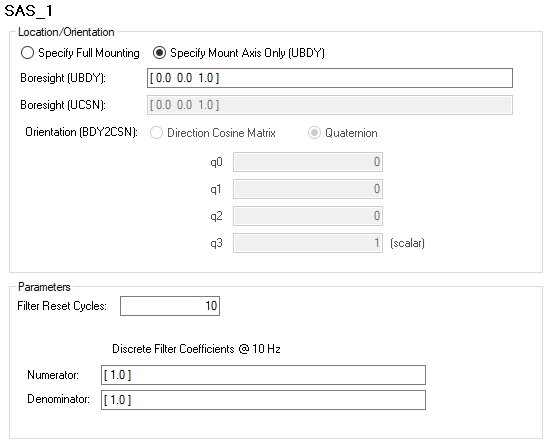
Sun angle sensors
Sun angle sensors are used for attitude determination and pointing of solar panels. Often, two or more sensors are placed on the spacecraft to provide a wider field of view during sun acquisition maneuvers. If you create two or more Sun angle sensors, a SunAngleSensor_Vector will appear in the Attitude Determination System Page. This new "sensor" represents the vector that is created from combining the data from multiple sun angle sensors.
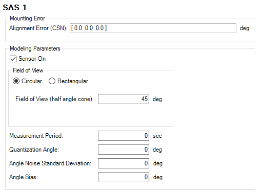
Sun angle sensors glossary
| Spacecraft Configuration Parameters | Description | Units |
|---|---|---|
| Boresight | If you select Specify Full Mounting, it defines the boresight relative to the CSN orientation. If you select Specify Mount Axis Only (UBDY), it defines the boresight relative to the spacecraft BDY frame. | N/A |
| Orientation | Three-axis angular orientation of the sensor frame defined as a DCM or quaternions, only available if you select Specify Full Mounting. | N/A |
| Filter Reset Cycles | Number of cycles allowed without a valid sensor measurement before filter resets | N/A |
| Discrete Filter | Defines order of sun sensor processing filter (typically a unity-gain low-pass filter). | N/A |
| ODySSy Simulation Parameters | Description | Units |
|---|---|---|
| Alignment Error (CSN) | Rotation angles from FSW measurement axis to true sensor orientation | deg |
| Sensor On | Sets hardware "on" state, which is useful for failure analysis. | N/A |
| Field of View | If you select Circular, it is the half cone angle defining width of sensor visibility. If you select Rectangular, the alpha direction is the X axis of the sensor boresight frame. The beta direction is the Y axis of the sensor boresight frame. The sensor boresight frame is defined as the sensor frame rotated such that the frame's Z axis is colinear with the sensor boresight. If the sensor boresight in the sensor frame is aligned with Z, then the sensor boresight frame and sensor frame are coincident. | deg |
| Measurement Period | Defines the rate at which the sensor updates measurements. | s |
| Quantization Angle | Measurement resolution of the sensor, entering "0" indicates no discretization of the true value | deg |
| Angle Noise Standard Deviation | Magnitude of injected white noise on sensed sun vector | deg |
| Angle Bias | Angle bias of scalar signal | deg |
Sun vector sensors
Sun vector sensors are similar to sun angle sensors but produce a vector instead of an angle. They are also used for attitude determination and pointing of solar panels. Often, two or more of these sensors are placed on the spacecraft to provide a wider field of view during sun acquisition maneuvers.
Sun vector sensors glossary

| Spacecraft Configuration Parameters | Description | Units |
|---|---|---|
| Boresight | If you select Specify Full Mounting, it defines the boresight relative to the Sun orientation. If you select Specify Mount Axis Only (UBDY), it defines the boresight relative to the spacecraft BDY frame. | N/A |
| Orientation | Three-axis angular orientation of the sensor frame defined as a DCM or quaternions, only available if you select Specify Full Mounting. | N/A |
| Filter Reset Cycles | Number of cycles allowed without a valid sensor measurement before filter resets | N/A |
| Discrete Filter (Sensor X/Y/Z Frame) | Defines order of sun sensor processing filter (typically a unity-gain low-pass filter). | N/A |
| Field of View | If you select Circular, it is the half cone angle defining the width of sensor visibility. If you select Rectangular, the alpha direction is the X axis of the sensor boresight frame. The beta direction is the Y axis of the sensor boresight frame. The sensor boresight frame is defined as the sensor frame rotated such that the frame's Z axis is colinear with the sensor boresight. If the sensor boresight in the sensor frame is aligned with Z, then the sensor boresight frame and sensor frame are coincident. | deg |

| ODySSy Simulation Parameters | Description | Units |
|---|---|---|
| Alignment Error (SUN) | Rotation angles from FSW measurement axis to true sensor orientation | deg |
| Sensor On | Sets hardware "on" state, which is useful for failure analysis. | N/A |
| Field of View | If you select Circular, it is the half cone angle defining width of sensor visibility. If you select Rectangular, the alpha direction is the X axis of the sensor boresight frame. The beta direction is the Y axis of the sensor boresight frame. The sensor boresight frame is defined as the sensor frame rotated such that the frame's Z axis is colinear with the sensor boresight. If the sensor boresight in the sensor frame is aligned with Z, then the sensor boresight frame and sensor frame are coincident. | deg |
| Measurement Period | Defines the rate at which the sensor updates measurements. | s |
| Angular Noise Standard Deviation | Magnitude of injected white noise on sensed sun vector | deg |