Geometry Constraints
Geometry constraints enable you to impose constraints that relate to scenario geometry. You can also opt to exclude time intervals that satisfy a given constraint.
The table below describes the Geometry constraints, including the objects you can apply them to.
When an access involves a child object (i.e., sensor, transmitter, receiver, antenna, or radar), use the child object's parent or grandparent in the table below to determine whether the constraint can be used for access to that child object. For example, if a constraint can be used for accesses to all vehicles, then that constraint can also be used for any child object of a vehicle.
In the following table, abbreviations in the Constraints used for accesses to... column are:
| F = facility | Pl = place | T = target | V = all vehicles | AT = area target |
| LT = line target | P = planet | St = star |
| Constraint | Description | Constraint used for accesses to... |
|---|---|---|
| 3DTiles Mask | If you select this check box, access to the object is constrained by any 3D Tileset data in the line of sight to which access is being calculated. | F Pl T P St V |
| Altitude | Access to the object is constrained by minimum and maximum altitude specified by the constraint. For cases in which ships or ground vehicles have a constant altitude that is near or equal to the minimum altitude constraint, numerical noise may determine access times and yield no access. In these circumstances, you should set the minimum altitude value to just under the desired constraint. For example, for a desired minimum constraint of 50 m, set the minimum altitude to 49.99m so that the object will show access when at the exact desired minimum constraint altitude. |
All |
| Background | Constrain access periods based on whether the Earth is or is not in the background. For example, you can use this constraint to limit access from the satellite to another vehicle.
You can only choose one of the following:
|
V |
|
Central Distance |
Central Distance provides a simple measure of physical separation using the angle implied by the maximum radius of the central body of the object owning the constraint. Central Distance isn't the true distance between projections of the position vectors on the central body's surface. The true distance would account for oblateness of the central body. This constraint does not do that. You can apply this constraint whenever the object involved in the access is not an AreaTarget or LineTarget. |
F, T, Pl, V, P, St |
| Cross Track Range | The Min and Max values represent a range that corresponds to the cross-track angle measured on a sphere with radius R_avg. The value approximates the surface distance of the direction of the target object from ground track. For more information, see the Cross Track Range and In Track Range constraints section. | F, T, Pl, V |
| Distance From Boundary |
Access is constrained by the signed distance from an area target boundary to the subpoint of the other object, measured along the central body surface (terrain is ignored) and meeting the specified minimum and maximum limits. The distance is first computed as the smallest distance between the subpoint and any point of the area target boundary. Then, if the subpoint lies within the boundary, the value is made negative; if the subpoint lies outside the boundary, the value is made positive. The sign is used to restrict the location of the subpoint when meeting the limits. For example:
|
F Pl T P St V |
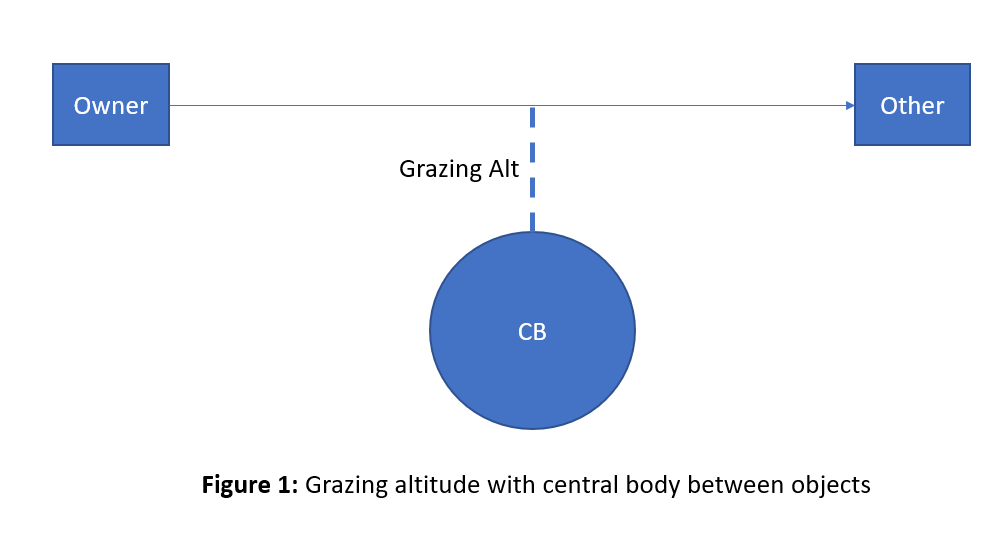
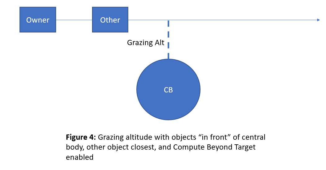
| Grazing Altitude |
This is defined as the nearest distance that the line of sight between the satellite and the other object comes to the Earth. Use this constraint to prevent a communications link between the two objects from moving too far down into the atmosphere, which might degrade the quality of the link.
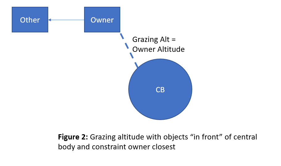
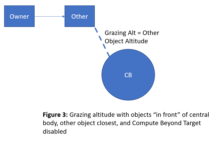
Mode 1: Compute Beyond Target check box cleared In this mode, the grazing altitude is evaluated strictly along the path between the constraint owner's position and the other object's position. If both objects are "in front", relative to the center of the Earth, then the constraint will return a value equal to the altitude of the object closer to the earth (see Figure 2 and Figure 3). It does not extend the vector past the other object’s position to see if that results in a smaller grazing altitude. An example of when this might occur is a GEO satellite looking down at a missile launch.
Mode 2: Compute Beyond Target check box selected In this mode, the grazing altitude is evaluated along the vector from the constraint owner’s position toward the other object extended past the other object’s position. If both objects are "in front", relative to the center of the Earth, then the constraint will return one of the following:
|
P St V |
|
|
||
|
|
||
|
|
||
|
|
||
| Ground Sample Distance | For a description, see the Ground Sample Distance constraint section of this topic. | F, T, P, V, AT |
| Ground Track | This constrains access to either the Ascending or the Descending side of the satellite's ground track. The ascending side of the ground track is defined as the portions of the ground track where the Earth-fixed latitude is increasing. The Earth-fixed latitude decreases on the descending side of the ground track. | F Pl T AT P St V |
| Height Above Horizon |
Enter the Min, Max, or both for the height of the facility, place, or target above the horizon. |
F, T, Pl, V |
| In Track Range | This is the (signed) range corresponding to the in-track angle, measured on a sphere with radius R_avg. The value approximates the surface distance along the ground track between the vehicle's direction V and the projection of the target's position vector onto the ground track (approximated as P). Values are positive when P is forward of V (i.e., when the relative position of the target object has a positive X-component value), and negative when P is behind V (i.e., a negative X-component value). For more information, see the Cross Track Range and In Track Range constraints section. | F, T, Pl, V |
| Propagation Delay | Access to the object is constrained by the minimum and maximum time it takes the signal to travel between the two objects. | F Pl T V |
| Range Rate | Range rate is the component of the relative velocity along the line of sight of the two objects. | F Pl T V |
Cross Track Range and In Track Range constraints
Cross Track Range and In Track Range are targeting constraint options. When applying these constraints, STK measures the location of the target object (often an object on the ground) relative to the central body-fixed (CBF) VVLH frame of a vehicle. STK computes the CBF VVLH frame using the vehicle's CBF position and velocity, with axes defined as follows:
- Z axis aligned with centric nadir (i.e., opposite to the position vector)
- Y axis opposite to the direction of the cross product of position with velocity
- X axis aligned with the tangential component of velocity (i.e., the velocity component perpendicular to the position vector)
In these axes, the cross-track direction is associated with the Y axis and the in-track direction is associated with the X axis. The terms cross-track and in-track for satellites are usually based upon the central body inertial VVLH frame, where velocity is measured with respect to inertial axes. However, for targeting constraints, STK uses the CBF VVLH frame.
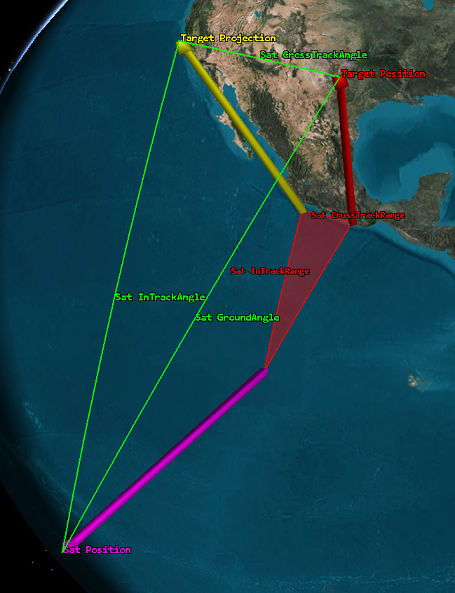
Let V denote the vehicle's position vector, T denote the target object's position vector, and let the vector P denote the projection of the target object's position vector into the X-Z plane. The directions VPT form a spherical right triangle (with right angle at P), where the angle between V and P is the in-track angle and the angle between P and T is the cross-track angle. The in-track angle is measured in the X-Z plane, while the cross-track angle is measured perpendicular to the X-Z plane.
STK associates a range with each angle by multiplying the angle (in radians) by the radius R_avg, which is the average distance to the vehicle's central body surface from its origin, along the V and T directions, calculated as:
R_avg = 0.5 *(R_Vp + R_Tp)
where
Vp locates the centric subpoint of the vehicle V.
R_Vp is the magnitude of Vp's position vector.
Tp locates the centric subpoint of the target object T.
R_Tp is the magnitude of Tp's position vector.
STK uses a sphere of radius R_avg to approximate the vehicle’s central body shape, for the purpose of computing distance along the surface between the directions V, P, and T.
When the vehicle is a satellite, the X-Z plane serves as a proxy for the plane tangent to the ground track. The ground track itself remains close to this plane near the satellite's centric subpoint, and so this plane is also a proxy for making measurements relative to the ground track itself. This is especially true for ground targets that are within line of sight to the satellite, since they are not too far forward or behind it.
The following diagram illustrates the Cross Track Range and In Track Range targeting constraint options described above.
Ground sample distance
Ground sample distance is the smallest size of an object on the ground that a sensor can detect. You can place a Ground Sample Distance constraint on a sensor object or on an object (other than AreaTarget) for which access from a sensor is being computed. A sensor must be involved in the access computation for this constraint to apply. The Ground Sample Distance constraint is based upon the access geometry and the physical attributes of the sensor. Enter the minimum and maximum Ground Sample Distance (GSD) in the units of measurement specified at the scenario level.
The most common application of GSD is from an elevated sensor (aircraft or spacecraft) looking at an object on the ground. The sensor is modeled as capturing an array of pixels, where each pixel has the same sized square shape when projected in front of the sensor. The sensor is also assumed to be pointed directly at the target. When the sensor is looking straight down on the target, the size of the pixel on the ground is simply the size of the square projected to the distance of the ground. As a single pixel is the smallest element of the image, GSD represents the smallest discernible feature size in the image.
The Ground Sample Distance computation is a function of the elevation angle at the location of the target object for object classes which are considered to be located at or near the ground. When the sensor is not looking straight down, the footprint of the pixel is not square on the ground. Instead, it is rectangular with elongation along the direction from the parent object sub-point to the sensor target. In this case, the GSD is defined as the longer dimension of the rectangle. The group of ground-oriented objects contains all fixed location objects and all vehicle objects with the exception of LaunchVehicles and Satellites.
For Launch Vehicle and Satellite objects, the expectation that the direction of interest for computing resolution is in the local horizontal plane is dropped, thus removing the dependence on the elevation angle. In this case, the GSD is always computed as if the sensor were viewing the target from an elevation angle of 90 degrees. This decision in the GSD model is made to reflect the ability of the sensor to detect features on the side of the target object facing the sensor.