Reference Plane Format
Use the format in this topic to create a reference plane pattern to model a sensor's field-of-view limitations. After you create the pattern, you can save it to a pattern file. You can then import the pattern file into STK, which will read the description contained in the pattern file when the file is referenced by a sensor.
As an example for this topic, you could use the reference plane format to create a sensor with the following specifications:
- The sensor is pointing off the right side of a vehicle with a beam from 40 degrees to 50 degrees off nadir.
- The sensor sweeps forward and aft 30 degrees.
- It is assumed that the vehicle's attitude is such that the vehicle X axis is along the velocity direction, which means that the custom sensor pattern is centered around a vehicle azimuth of 90 degrees.
- The sensor is designed so that the reference direction (boresight) is along nadir and, therefore, is outside of the pattern.
After you create the pattern, you can save it to a pattern file. You can then import the pattern file into STK. STK will read the description contained in the pattern file when the file is referenced by a sensor.
The accuracy of computations performed using custom sensors is directly related to the number of points used to describe the pattern. It is generally better to spend additional time generating a well-defined pattern than to be uncertain of the fidelity of the results.
In the reference plane format, the custom sensor pattern is defined by the intersection of the sensor's projection with a plane perpendicular to the sensor reference direction (boresight) at a specified distance from the origin of the sensor. The intersection is described in polar coordinates.
In the following figure,  and
and  define the sensor elevation sweep angles from nadir, in this case 40 degrees and 50 degrees respectively. The angles
  and
and  define the forward and aft sweep, in this case both 30 degrees.
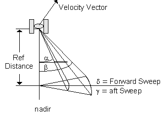
The desired relative geometry of the satellite and the custom sensor pattern
The location of the reference plane is measured relative to the sensor location and is not the same as the distance from the sensor to the surface of the Earth.
The following figure uses polar coordinates to show the sensor as it would appear in the reference plane. The center of the plot represents the origin of the vehicle nadir vector and 0 degrees of the polar plot represents the direction of the vehicle X axis (vehicle velocity direction).
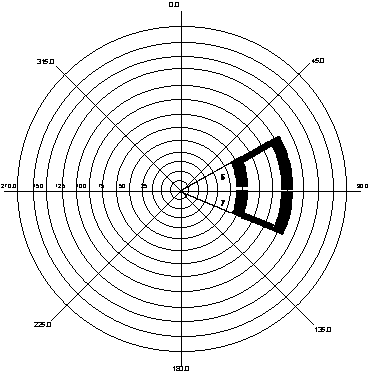
Reference plane shown in polar coordinates
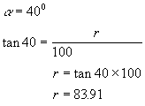
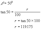
Radius values for the polar coordinates describing the custom sensor pattern are obtained by projecting the sweep angles, and , onto the reference plane. To do this, assign an arbitrary fixed distance from the reference plane to the vehicle. In this example, a value of 100 is used. To calculate r, use the following equation:
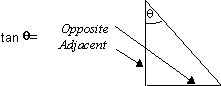
where Opposite equals r or the length of the line from the vehicle nadir vector to the sensor pattern edge, in the reference plane, and Adjacent equals the reference plane distance. For this example, the reference distance is 100 units.
The values of i for the two angles are calculated as follows:
|
|
Once you project the sensor pattern onto polar coordinates, read off a suitable number of points to describe the shape of the pattern. Each point is specific by r, the radial distance from the center, and  (theta), the angle measured from straight up, clockwise. The table shows the polar coordinates derived from this example.
Polar coordinates
| r | theta |
|---|---|
| 83.91 | 60.0 |
| 83.91 | 70.0 |
| 83.91 | 80.0 |
| 83.91 | 90.0 |
| 83.91 | 100.00 |
| 83.91 | 110.0 |
| 83.91 | 120.0 |
| 119.175 | 120.0 |
| 119.175 | 110.0 |
| 119.175 | 100.0 |
| 119.175 | 90.0 |
| 119.175 | 80.0 |
| 119.175 | 70.0 |
| 119.175 | 60.0 |
Create the custom pattern file. Now that you have the polar coordinates for your custom sensor pattern, create a new file in your STK Database (STKdb) directory. The file name should be a descriptive name of 20 characters or fewer.
After you create the file, open it using a standard text editor and enter the information in the format shown in the following table.
| Field | Description |
|---|---|
| Reference Distance | Enter the length of the line from the vehicle nadir vector to the sensor pattern edge, in the reference plane. |
| NumberPoints | Enter the total number of data points in the file. |
| PatternData | Provide the r/theta pairs. The first point and the last point must be the same so that the sensor pattern is closed. |
| EndPatternData |
You must have this keyword at the end of the file. |
AGI recommends using a convention such as a `.Pattern' extension for sensor pattern files.
Sample Custom Reference Plane Pattern File
stk.v.12.0
ReferenceDistance 100.0
NumberPoints 15
PatternData
83.91 60.0
83.91 70.0
83.91 80.0
83.91 90.0
83.91 100.00
83.91 110.0
83.91 120.0
119.175 120.0
119.175 110.0
119.175 100.0
119.175 90.0
119.175 80.0
119.175 70.0
119.175 60.0
83.91 60.0
EndPatternData