STK Premium (Space) or STK Enterprise
You can obtain the necessary licenses for this tutorial by
The results of the tutorial may vary depending on the user settings and data enabled (online operations, terrain server, dynamic Earth data, etc.). It is acceptable to have different results.
Capabilities covered
This lesson covers the following capabilities of the Ansys Systems Tool Kit® (STK®) digital mission engineering software:
- STK Pro
- Astrogator
Problem statement
Engineers and operators require a quick way to design high-fidelity spacecraft trajectories for mission planning and operations. Like any other orbital regime, geosynchronous orbits (GEO) are subject to various perturbing forces that impact the stability of GEO satellites in terms of their position, or "slot" above a particular point on the Earth's surface. The main sources of perturbation are the Earth’s non-spherical geopotential, solar radiation pressure, and third body effects—mainly the Moon and the Sun. The overall effect is a longitudinal drift, whose direction depends on the longitude itself, and changes in inclination over time.
Solution
Use the STK/Astrogator® capability to design and perform station-keeping maneuvers using Automatic Sequences. Visualize the satellite's GEO slot using a geostationary box to track the satellite's drift. Create an Automatic Sequence for East-West station-keeping maneuvers based on longitude control and an Automatic Sequence for North-South station-keeping maneuvers based on pure inclination control. Attitude disturbances may also be present, but are not covered in this tutorial.
What you will learn
Upon completion of this tutorial, you will be able to:
- Visualize a reference GEO slot using a geostationary box
- Create and use a new VVLH coordinate system
- Create and configure an East-West station-keeping Automatic Sequence
- Create and configure a North-South station-keeping Automatic Sequence
- Analyze station-keeping maneuvers using reports and graphs
Video guidance
Watch the following video. Then follow the steps below, which incorporate the systems and missions you work on (sample inputs provided).
Creating a new scenario
First, you must create a new scenario, and then build from there. Create a 450-day analysis period. This is a good time span to evaluate how many times station-keeping maneuvers are required during an extended period of operation.
- Launch the STK application (
 ).
). - Click
 Create a Scenario when the Welcome to STK dialog box opens.
 - Enter the following in the STK: New Scenario Wizard:
- Click when you finish.
- Click Save (
 ) when the scenario loads. The STK application creates a folder with the same name as your scenario for you.
 - Verify the scenario name and location in the Save As dialog box.
- Click .
| Option | Value |
|---|---|
| Name | GEO_Station_Keeping |
| Start | 1 Apr 2025 00:00:00.000 UTCG |
| Stop | + 450 days |
Save (![]() ) often during this scenario!
) often during this scenario!
Creating a geostationary box
You can visualize a
Inserting a reference Satellite object
Insert a Satellite object using the Orbit Wizard method. You will use this Satellite object as a stationary reference point to center the geostationary box.
- Bring the Insert STK Objects tool (
 ) to the front.
 - Select Satellite (
 ) in the Select An Object To Be Inserted list.
 - Select Orbit Wizard (
 ) in the Select A Method list.
 - Click .
Using the Orbit Wizard
The
- Open the Type drop-down list when the Orbit Wizard opens.
- Select Geosynchronous.
- Enter Reference in the Satellite Name field.
- Enter 13 deg in the Subsatellite Point field in the Definition panel.
- Click to accept your changes and to close the Orbit Wizard.
Setting the 3D Graphics window reference frame
Set the reference frame to Fixed by Window. It is fixed with respect to the central body in the 3D Graphics window.
- Right-click on Reference () in the Object Browser.
- Select Properties (
 ) in the shortcut menu.
 - Select the 3D Graphics - Orbit System page when the Properties Browser opens.
- Select the Show check box for the Fixed by Window system.
- Clear the Show check box for the Inertial by Window system.
- Click to accept your changes and to keep the Properties Browser open.
Configuring the geostationary box's display
In a real operational model, the North-South / East-West geostationary box would be small (0.05 deg × 0.05 deg). For this tutorial you will use a simpler model with a box that is an order of magnitude larger.
- Select the 3D Graphics - Proximity page.
- Select the Show check box in the Geostationary Box panel.
- Set the following parameters:
- Open the Color drop-down list.
- Select white.
- Click to accept your changes and to keep the Properties Browser open.
| Option | Value |
|---|---|
| Longitude | 13 deg |
| North/South | 0.5 deg |
| East/West | 0.5 deg |
| Radius | 42166.3 km |
Removing labels and orbits from the 2D and 3D Graphics windows
You have some labels and orbit lines you want to remove from the 2D and 3D Graphics windows.
- Select the 2D Graphics - Attributes page.
- Clear the Inherit from Scenario check box in the Inheritable Settings panel.
- Clear the Show Label and Show Orbit check boxes.
- Click to accept your changes and to close the Properties Browser.
Viewing the geostationary box in the 3D Graphics window
Look at Reference box in the 3D Graphics window.
- Bring the 3D Graphics window to the front.
- Right-click on Reference () in the Object Browser.
- Select Zoom To in the shortcut menu.
- Use your mouse to zoom out and view the geostationary box.
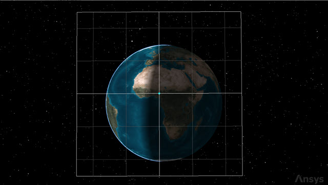
geostationary box
Modeling the geostationary satellite
Insert a second Satellite object and name it GEO_Sat.
- Insert a Satellite () object using the Insert Default () method.
- Right-click on Satellite2 () in the Object Browser.
- Select Rename in the shortcut menu.
- Rename Satellite2 () GEO_Sat.
Changing the propagator to Astrogator
The
- Open GEO_Sat's () Properties ().
- Select the Basic - Orbit page when the Properties Browser opens.
- Open the Propagator drop-down list.
- Select Astrogator.
Setting the Initial State segment
Use the
- Select Initial State (
 ) in the MCS.
 - Open the Coordinate Type drop-down list.
- Select Keplerian.
- Ensure the Orbit Epoch matches your scenario start time (for example, 1 Apr 2025 00:00:00.000 UTCG).
- Open the Right Asc. of Asc. Node drop-down list in the Element Type list.
- Select Lon. of Asc Node.
- Set the following Element Type parameters:
- Click to accept your changes and to keep the Properties Browser open.
| Option | Value |
|---|---|
| Semi-major Axis | 42166.3 km |
| Eccentricity | 0 |
| Inclination | 0 deg |
| Lon. of Asc. Node | 13 deg |
| Argument of Periapsis | 0 deg |
| True Anomaly | 202 deg |
As you enter the values of the orbital elements, some of the values will updated automatically due to math changes inside of the STK application.
Setting the Propagate segment
Use the
After each step, the segment checks to see if any stopping conditions were met during the step. If so, it then finds the exact point, within tolerance, where the stopping condition is satisfied. From that point, the segment either executes an automatic sequence or stops the propagation and passes the state at that point to the next segment. Astrogator also adds an ephemeris point at the time that the stopping condition is triggered.
- Select Propagate (
 ) in the MCS.
 - Enter 450 day in the Trip field.
- Clear the Condition Inherited by Automatic Sequences check box.
- Click to accept your changes and to keep the Properties Browser open.
Clearing this check box will allow Automatic Sequences in the segment to ignore the Propagate segment's stopping conditions while they are executing.
Adding a VVLH orbit system
Add a
- Select the 3D Graphics - Orbit System page.
- Click .
- Select Reference () in the Select Object VVLH System dialog box.
- Click to accept your selection and to close the Select Object VVLH System dialog box.
- Clear the Show check box for the Inertial by Window system.
- Click to accept your changes and to keep the Properties Browser open.
Setting the 3D Graphics Pass settings
Update the
- Select the 3D Graphics - Pass page.
- Open the Lead Type drop-down list in the Orbit Track panel.
- Select None.
- Open the Trail Type drop-down list.
- Select Time.
- Enter 720 hr in the Trail Type field.
- Click to accept your changes and to keep the Properties Browser open.
This option does not display the leading or trailing portion.
This option specifies the amount of time that the leading or trailing portion is displayed.
Running the Mission Control Sequence
To calculate the trajectory of the spacecraft you must run the Mission Control Sequence. Astrogator will proceed through the MCS and run each segment, generating an ephemeris for the spacecraft. As it runs the MCS, Astrogator carries the trajectory and state of the spacecraft determined so far from one segment to the next. Using the Run Active profiles option runs the mission control sequence allowing the active profiles to operate.
- Select the Basic - Orbit page.
- Click Run Entire Mission Control Sequence (
 ) in the MCS toolbar.
 - Click Clear Graphics (
 ) in the MCS toolbar.
 - Click to accept your changes and to keep the Properties Browser open.
Viewing the orbit in the 3D Graphics window
You can increase your animation time step and animate the scenario to view the orbit in the 3D Graphics window.
- Bring the 3D Graphics window to the front.
- Zoom to GEO_Sat ().
- Click Increase Time Step (
 ) in the Animation toolbar and set the time step to 7200.00 sec.
 - Click Start (
 ) to animate the scenario.
 - Click Reset (
 ) when finished.
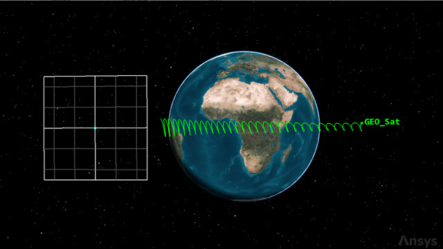
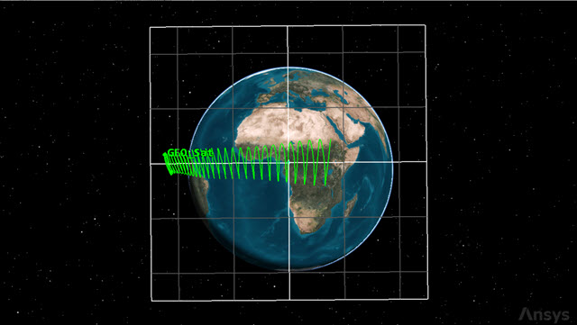
initial orbit change
The inclination change over time is mainly due to the third-body perturbations, and it could vary depending on the initial epoch you set for the scenario. The satellite also drifts eastward; this could change if you change the initial longitude slot.
Creating custom Calculation Object components
You want to keep GEO_Sat within the boundaries of the geostationary box. Some of the parameters you will use must be created in the Component Browser. You will use a custom
- Return to GEO_Sat's () Properties ().
- Select the Basic - Orbit page.
- Click Component Browser (
 ) in the MCS toolbar.
 - Expand (
 ) the Calculation Objects (
 ) folder in the Show Component Type list when the Component Browser dialog box opens.
 - Select Keplerian Elems ().
- Select Inclination (
 ) in the Keplerian Elems list.
 - Click Duplicate component (
 ) in the Keplerian Elems toolbar.
 - Enter TOD Inclination in the Name field when the Field Editor dialog box opens.
- Click to accept your change and to close the Field Editor dialog box.
Note that Inclination is a read-only component.
Using the TrueOfDate frame
You can create new components in the TrueOfDate (TOD) frame. You can modify the TOD Inclination component you created by setting it to use the
- Double-click on TOD Inclination (
 ) in the Keplerian Elems list.
 - Double-click on the CoordSystem row when the Keplerian Elems - TOD Inclination dialog box opens.
- Select Earth (
 ) in the object tree when the Select Reference dialog box opens.
 - Select TOD (
 ) in the Systems for: Earth list.
 - Click to accept your selection and to close the Select Reference dialog box.
- Click to accept your changes and to close the Keplerian Elems - TOD Inclination dialog box.
- Click to close the Component Browser.
Modeling an East-West station-keeping Automatic Sequence
Since the satellite is drifting eastward, the maneuver to implement the orbit should reduce the angular speed while initiating a westward drift. If you fire along the velocity direction, you are going to increase the semi-major axis and reduce the orbital angular speed.
After the burn, the satellite starts drifting westward. However, since the disturbing forces are always present, the drift is reduced over time. After some time there is a turnaround point, where the effects of the burn are nullified by the perturbing forces. Eventually, the satellite starts to drift eastward again and the cycle repeats itself.
The required Delta-V magnitude can be calculated to set the satellite's turnaround point at the western border of the station-keeping box; with this strategy you can minimize the number of burns executed. Model these calculations using an Automatic Sequence.
Creating a new Automatic Sequence
- Click Automatic Sequence Browser (
 ) in the MCS toolbar.
 - Click when the Automatic Sequence Browser dialog box opens.
- Enter EW Station Keeping in the Name field when the Field Editor dialog box opens.
- Click to accept your change and to close the Field Editor dialog box.
Inserting a Sequence segment
Use a
- Select EW Station Keeping in the Automatic Sequence Browser dialog box.
- Click .
- Click Insert Segment After (
 ) in the MCS toolbar when the Automatic Sequence Properties dialog box opens.
 - Select Sequence (
 ) in the Segment Selection dialog box.
 - Click to accept your selection and to close the Segment Selection dialog box.
- Right-click on Sequence () in the MCS.
- Select Rename in the shortcut menu.
- Rename Sequence () East West Station Keeping.
Inserting a Propagate segment
Create a new Propagate segment and nest it in the Sequence segment.
- Click Insert Segment After () in the MCS toolbar of the Automatic Sequence Properties dialog box.
- Select Propagate () when the Segment Selection dialog box opens.
- Click to accept your selection and to close the Segment Selection dialog box.
- Click and drag Propagate () to nest it in East West Station Keeping () Sequence in the MCS.
- Select Propagate () in the MCS.
- Click Segment Properties () in the MCS toolbar.
- Enter Stop on Apoapsis in the Name field of the Edit Segment dialog box.
- Open the Color drop-down list.
- Select a color that's different from the other Propagate () segments in the scenario.
- Click to accept your changes and to close the Edit Segment dialog box.
Creating a new stopping condition
Add an apoapsis stopping condition to the Propagate segment to stop the propagation when the satellite reaches the point farthest from the origin.
- Click New... () in the Stopping Conditions panel toolbar.
- Select Apoapsis () when the New Stopping Condition dialog box opens.
- Click to accept your selection and to close the New Stopping Condition dialog box.
- Select the Duration stopping condition.
- Click Delete (
 ) in the Stopping Conditions panel toolbar.
Inserting a Target Sequence
Insert a
- Click Insert Segment After () in the MCS toolbar of the Automatic Sequence Properties dialog box.
- Select Target Sequence (
 ) when the Segment Selection dialog box opens.
 - Click to accept your selection and to close the Segment Selection dialog box.
- Right-click on Target Sequence () in the MCS.
- Select Rename in the shortcut menu.
- Rename Target Sequence () Target Turn Around.
Inserting a Maneuver segment
Use a
- Click Insert Segment After () in the MCS toolbar of the Automatic Sequence Properties dialog box.
- Select Maneuver (
 ) when the Segment Selection dialog box opens.
 - Click to accept your selection and to close the Segment Selection dialog box.
- Click and drag Maneuver () to nest it under Target Turn Around ().
- Click Segment Properties () in the MCS toolbar.
- Enter Target Turn Around in the Name field when the Edit Segment dialog box opens.
- Open the Color drop-down list.
- Select white.
- Click to accept your changes and to close the Edit Segment dialog box.
Inserting a Propagate segment
Create a new Propagate segment after the East West Burn segment in the Target Sequence.
- Click Insert Segment After () in the MCS toolbar when the Automatic Sequence Properties dialog box opens.
- Select Propagate () when the Segment Selection dialog box opens.
- Click to accept your selection and to close the Segment Selection dialog box.
- Click Segment Properties () in the MCS toolbar.
- Enter Prop to Second Node in the Name field when the Edit Segment dialog box opens.
- Open the Color drop-down list.
- Select a color that's different from the other Propagate () segments in the scenario.
- Click to accept your changes and to close the Edit Segment dialog box.
Inserting a return segment
Use a
- Click Insert Segment After () in the MCS toolbar of the Automatic Sequence Properties dialog box.
- Select return (
 ) when the Segment Selection dialog box opens.
 - Click to accept your selection and to close the Segment Selection dialog box.
- Select the Enable (except Profiles bypass) option.
Selecting the Enable (except Profiles bypass) option causes the return segment to be active except when run from a Target Sequence profile (for example, a differential corrector), which will ignore it.
Inserting a second Propagate segment
Add another Propagate segment after the return segment.
- Click Insert Segment After () in the MCS toolbar of the Automatic Sequence Properties dialog box.
- Select Propagate () when the Segment Selection dialog box opens.
- Click to accept your selection and to close the Segment Selection dialog box.
- Click Segment Properties () in the MCS toolbar.
- Enter Prop to Ascending Node in the Name field when the Edit Segment dialog box opens.
- Open the Color drop-down list.
- Select a color that's different from the other Propagate () segments in the scenario.
- Click to accept your changes and to close the Edit Segment dialog box.
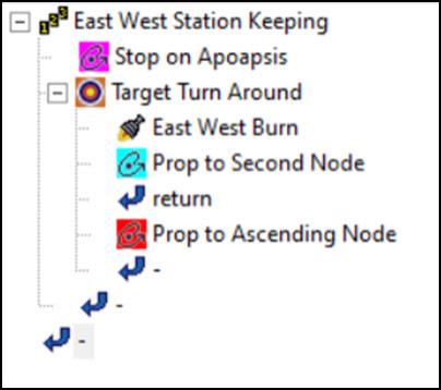
Automatic Sequence MCS view
By including the Return segment in the sequence and setting it to bypass, the Prop to Ascending Node Propagate segment is only run before the convergence of the differential corrector.
Defining the East West Burn maneuver
When at apogee, the East West Burn segment initiates a burn whose Delta-V magnitude is a control parameter.
- Select East West Burn () in the MCS.
- Ensure the Attitude tab is selected.
- Open the Attitude Control drop-down list.
- Select Thrust Vector.
- Click the X (Velocity) target (
 ) to make it a control parameter.
Defining the Prop to Second Node Propagate segment
After initiating a burn, set the propagator to run until the second node is reached; this is because you want to wait some time before checking for a result. At this point, the satellite will be drifting eastward.
- Select Prop to Second Node () in the MCS.
- Click New... () in the Stopping Conditions panel toolbar.
- Select AscendingNode () when the New Stopping Condition dialog box opens.
- Click to accept your selection and to close the New Stopping Condition dialog box.
- Select the Duration stopping condition.
- Click Delete () in the Stopping Conditions panel toolbar.
- Enter 2 in the Repeat Count field.
The Repeat Count field is active for those stopping conditions capable of being satisfied more than once. It specifies the number of times the condition must be satisfied before the condition is considered to be met. By setting it to 2, GEO_Sat will propagate until the second node is reached.
Setting the coordinate system
The Coord. System field is interchangeable with the Central Body and Reference Point fields and is used only for stopping conditions that take the coordinate system into account (for example, Argument of Latitude). The default coordinate system of a stopping condition is Earth Inertial.
- Click the Coord. Systems ellipsis (
 ).
). - Select Earth () in the object tree when the Select Reference dialog box opens.
- Select TOD () in the Systems for: Earth list.
- Click to accept your selection and to close the Select Reference dialog box.
Defining the Prop to Ascending Node Propagate segment
Add an AscendingNode stopping condition to the Prop to Ascending Node segment.
- Select Prop to Ascending Node () in the MCS.
- Click New... () in the Stopping Conditions panel toolbar.
- Select AscendingNode () when the New Stopping Condition dialog box opens.
- Click to accept your selection and to close the New Stopping Condition dialog box.
- Select the Duration stopping condition.
- Click Delete () in the Stopping Conditions panel toolbar.
Setting the coordinate system
As with the Prop to Second Node Propagate segment, set the Prop to Ascending Node Propagate segment to use the Earth TOD coordinate system.
- Click the Coord. Systems ellipsis ().
- Select Earth () in the object tree when the Select Reference dialog box opens.
- Select TOD () in the Systems for: Earth list.
- Click to accept your selection and to close the Select Reference dialog box.
Defining a Constraint component
Add a
- Click the ellipsis () in the Constraints panel.
- Select UserDefined () in the Available Components list when the Select Constraints dialog box opens.
- Click Insert Component (
 ).
). - Double-click on the ComponentName entry in the Component Details list.
- Enter Min Longitude in the Name field when the String Field dialog box opens.
- Click to accept your change and to close the String Field dialog box.
Setting the constraint criteria
Set the criteria for the condition to be met.
- Double-click on the Criteria entry in the Component Details list.
- Open the Selection drop-down list when the Listbox Field dialog box opens.
- Select Greater Than Minimum.
- Click to accept your selection and to close the Listbox Field dialog box.
The Greater Than Minimum criterion assures that the propagation will take place until the turnaround point and, when the satellite starts drifting eastward once again, it is stopped as soon as an ascending node is met.
Setting the calculation component
Select the calculation object component used to perform the calculation to evaluate the condition.
- Double-click on the CalcObject entry.
- Click the Component ellipsis () when the Embedded Component Link Selection dialog box opens.
- Select Geodetic - Longitude () when the Select Component dialog box opens.
- Click to accept your selection and to close the Select Component dialog box.
- Click to accept your changes and to close the Embedded Component Link Selection dialog box.
The Longitude calculation object calculates the longitude with respect to the central body.
Setting the tolerance
The tolerance value sets the accuracy of the final point to the desired value.
- Double-click on the Tolerance entry.
- Enter 0.05 deg in the Real field when the Real Number Field dialog box opens.
- Click to accept your change and to close the Real Number Field dialog box.
- Click to accept your changes and to close the Select Constraints dialog box.
Setting the results
Set a minimum value for Astrogator to report and target for the Prop to Ascending Node segment.
- Click .
- Expand () the Math () folder in the Available Components list when the User-Selected Results - Prop to Ascending Node dialog box opens.
- Select Minimum Value ().
- Click Insert Component ().
- Double-click on Minimum Value in the Name entry.
- Enter Minimum Longitude in the Name field of the Field Editor dialog box.
- Click to accept your change and to close the Field Editor dialog box.
Setting the calculation object
Select the component used to perform a calculation to evaluate the condition.
- Double-click on the CalcObject entry in the Component Details list.
- Expand () Geodetic () folder when the Component Selection dialog box opens.
- Select Longitude ().
- Click to accept your selection and to close the Component Selection dialog box.
- Click to accept your changes and to close the User-Selected Results - Prop to Ascending Node dialog box.
Configuring the differential corrector
Start by setting the control parameters. GEO_Sat will be conducting small adjustments to maintain the orbit. You want the Max Step and Perturbation to be on a similar scale.
- Select the Target Turn Around () in the MCS.
- Click Properties... () in the Profiles panel.
- Select the Use check box for the ImpulsiveMnvr.Pointing.Cartesian.X control parameter in the Control Parameters panel.
- Enter 0.01 m/sec in the Perturbation field.
- Enter 1 m/sec in the Max. Step field.
Perturbation is the value that you want the profile to use in calculating numerical derivatives.
The Max Step is the maximum increment to the value of the parameter in a step.
Setting the Equality Constraints (Results)
GEO_Sat will maneuver through the whole of the geostationary box's bounds. You want to allow for a guard band by setting the desired value of the minimum longitude to 12.55 deg.
- Select the Use check box for the Minimum_Longitude result in the Equality Constraints (Results) panel.
- Double-click on the Desired Value entry.
- Enter 12.55 deg.
- Enter 0.001 deg in the Tolerance field.
- Click to accept your changes and to close the Differential Corrector dialog box.
Setting the action
Using Run active profiles runs the mission control sequence allowing the active profiles to operate.
- Open the Action drop-down list.
- Select Run active profiles.
- Click to accept your changes and to close the Automatic Sequence Properties dialog box.
Modeling a North-South station-keeping Automatic Sequence
Inclination correction requires much more fuel than the in-plane correction, so a good strategy is necessary to save fuel and increase the satellite's operational life. You can create an automatic Target Sequence to implement a basic procedure in which you wait until an appropriate time to initiate a burn along the velocity and orbit normal directions to reduce the inclination while also keeping a circular, geosynchronous orbit (pure inclination control). Other techniques include RAAN control, in which you change the RAAN to get an inclination reduction over time.
Creating a new Automatic Sequence
Create a second Automatic Sequence, which will correct for the Satellite object's inclination.
- Click in the Automatic Sequence Browser dialog box.
- Enter NS Station Keeping in the Name field of the Field Editor dialog box.
- Click to accept your change and to close the Field Editor dialog box.
Adding a Target Sequence
Add a new Target Sequence tot he Automatic Sequence.
- Select NS Station Keeping in the Automatic Sequence Browser dialog box.
- Click .
- Click Insert Segment After () in the MCS toolbar when the Automatic Sequence Properties dialog box opens.
- Select Target Sequence () in the Segment Selection dialog box.
- Click to accept your selection and to close the Segment Selection dialog box.
- Right-click on Target Sequence () in the MCS.
- Select Rename in the shortcut menu.
- Rename Target Sequence () North South SK Drift.
Inserting a Maneuver segment
Create a new Maneuver segment and nest it in the Target Sequence.
- Click Insert Segment After () in the MCS toolbar of the Automatic Sequence Properties dialog box.
- Select Maneuver () when the Segment Selection dialog box opens.
- Click to accept your selection and to close the Segment Selection dialog box.
- Click and drag Maneuver () to nest it inside North South SK Drift ().
- Select Segment Properties () in the MCS toolbar.
- Enter North South Burn in the Name field when the Edit Segment dialog box opens.
- Open the Color drop-down list.
- Select white.
- Click to accept your changes and to close the Edit Segment dialog box.
Defining the North-South station-keeping maneuver
When at ascending node, the North South station-keeping maneuver makes a burn with a Delta-V whose components are control parameters.
- Ensure the Attitude tab is selected.
- Open the Attitude Control drop-down list.
- Select Thrust Vector.
- Click the X (Velocity) target () to make it a control parameter.
- Click the Y (Normal) target () to make it a control parameter.
Defining the Results
Set a difference (Delta) value for Astrogator to report and target for the Maneuver segment.
- Click .
- Expand () the Math () folder in the Available Components list of the User-Selected Results - North South Burn dialog box.
- Select Difference ().
- Click Insert Component ().
- Double-click on Difference in the Name entry.
- Enter SMA Diff in the Name field when the Field Editor dialog box opens.
- Click to accept your change and to close the Field Editor dialog box.
Setting the calculation object
Select the component used to perform a calculation to evaluate the condition.
- Double-click on the CalcObject entry in the Component Details list.
- Expand () Keplerian Elems () when the Component Selection dialog box opens.
- Select Semimajor Axis ().
- Click to accept your selection and to close the Component Selection dialog box.
Inserting a second result
Select your custom TOD Inclination component as another user-selected result for the Maneuver segment.
- Expand () Keplerian Elems () in the Available Components list.
- Select TOD Inclination ().
- Click Insert Component ().
- Click to accept your changes and to close the User-Selected Results - North South Burn dialog box.
Defining the differential corrector profile
Set the Target Sequence's
- Select North_South_SK_Drift () in the MCS.
- Click Properties... () in the Profiles panel toolbar.
Setting the Control Parameters
Select both independent variables to use as control parameters control parameters for the differential corrector.
- Select the Use check box for the ImpulsiveMnvr.Pointing.Cartesian.X control parameter in the Control Parameters panel.
- Ensure 0.1 m/sec is set as the Perturbation.
- Enter 10 m/sec in the Max. Step field.
- Select the Use check box for the ImpulsiveMnvr.Pointing.Cartesian.Y control parameter
- Ensure 0.1 m/sec is set as the Perturbation.
- Enter 10 m/sec in the Max. Step field.
Setting the Equality Constraints (Results)
Select both dependent variables to use as equality constraints for the differential corrector.
- Select the Use check box SMA_Diff result in the Equality Constraints (Results) panel.
- Enter 0.01 km in the Tolerance field.
- Select the Use check box for the TOD_Inclination result.
- Enter 0.001 deg in the Tolerance field.
Setting the scaling method
Scaling improves numerical behavior if the profile's enabled parameters have diverse magnitudes.
- Open the Method drop-down list in the Scaling panel.
- Select By tolerance.
- Click to accept your changes and to close the Differential Corrector dialog box.
Setting the Action
Define the profile for the action that the target sequence will take.
- Open the Action drop-down list.
- Select Run active profiles.
- Click to accept your changes and to close the Automatic Sequence Properties dialog box.
- Click to close the Automatic Sequence Browser dialog box.
- Click to accept your changes and to keep the Properties Browser open.
Using the Automatic Sequences
After defining the two station-keeping Automatic Sequences, you need to characterize the main Propagation segment. You must add a new stopping condition to limit for how long GEO_Sat will propagate.
In the meantime, two things can happen:
- GEO_Sat approaches the East-West border of the geostationary box, requiring a corrective East-West station-keeping maneuver
- GEO_Sat approaches the North-South border of the geostationary box, requiring a North-South station-keeping maneuver
Inserting a second stopping condition
Add an apoapsis stopping condition to trigger the EW Station Keeping Automatic Sequence.
- Select Propagate () in the MCS.
- Click New... () in the Stopping Conditions panel toolbar.
- Select Apoapsis () when the New Stopping Condition dialog box opens.
- Click to accept your selection and to close the New Stopping Condition dialog box.
Applying the EW Station Keeping Automatic Sequence
Set the EW Station Keeping Automatic Sequence to trigger when the stopping condition is satisfied.
- Click the Sequence ellipsis ().
- Select EW Station Keeping () in the Select Component dialog box.
- Click to accept your selection and to close the Select Component dialog box.
- Enter 3 in the Repeat Count field.
Setting the Propagator's time constraints
Use the Advanced options to specify constraints on the time period during which Astrogator will attempt to satisfy the Stopping Condition.
- Click .
- Enter 10 yr in the Maximum Propagation Time field of the Propagator Advanced dialog box.
- Click to accept your change and to close the Propagator Advanced dialog box.
Setting a Before stopping condition
Use a "before" stopping condition to define a stopping condition that depends on two events. Add a condition to limit the distance the spacecraft can travel in the longitudinal direction. Since you do not want to overshoot the border of your geostationary box, you can propagate to its border at 13.5-degree longitude, and then perform the maneuver at the apoapsis before the longitude limit is surpassed.
- Click the Before ellipsis ().
- Click New (
 ) when the Stop Before dialog box opens.
 - Select Longitude () in the New Stopping Condition dialog box.
- Click to accept your selection and to close the New Stopping Condition dialog box.
- Enter 13.55 deg in the Trip field.
- Click to accept your changes and to close the Stop Before dialog box.
Inserting a third stopping condition
Add an ascending node stopping condition to trigger the NS Station Keeping Automatic Sequence.
- Click New... () in the Stopping Conditions panel toolbar.
- Select AscendingNode () in the New Stopping Condition dialog box.
- Click to accept your selection and to close the New Stopping Condition dialog box.
Applying the NS Station Keeping Automatic Sequence
Set the NS Station Keeping Automatic Sequence to trigger when the stopping condition is satisfied.
- Click the Sequence ellipsis ().
- Select NS Station Keeping () in the Select Component dialog box.
- Click to accept your selection and to close the Select Component dialog box.
Setting the coordinate system
Select the Earth TOD as the coordinate system for the Propagate segment.
- Click the Coord. System ellipsis ().
- Select Earth () in the object tree when the Select Reference dialog box opens.
- Select TOD () in the Systems for: Earth list.
- Click to accept your selections and to close the Select Reference dialog box.
Setting a Constraint for north-south station-keeping
Add a constraint to limit the changes in GEO_Sat's inclination.
- Click the Constraints panel ellipsis ().
- Select UserDefined () in the Available Components list when the Select Constraints dialog box opens.
- Click Insert Component ().
- Double-click on the ComponentName entry in the Component Details field.
- Enter MaxInclination in the Name field when the String Field dialog box opens.
- Click to accept your change and to close the String Field dialog box.
Setting the criteria
Set the criteria for the condition to be met.
- Double-click on the Criteria entry in the Component Details list.
- Open the Selection drop-down list when the Listbox Field dialog box opens.
- Select Greater Than.
- Click to accept your selection and to close the Listbox Field dialog box.
Setting the calculation component
Select the component used to perform a calculation to evaluate the condition.
- Double-click on the CalcObject entry.
- Click the Component ellipsis () when the Embedded Component Link Selection dialog box opens.
- Expand () Keplerian Elems when the Select Component dialog box opens.
- Select TOD Inclination ().
- Click to accept your selection and to close the Select Component dialog box.
- Click to close the Embedded Component Link Selection dialog box.
Setting the TOD Inclination value
Set the value required to satisfy the condition.
- Double-click on the Value entry.
- Enter 0.45 deg in the Real field of the Real Number Field dialog box.
- Click to accept your change and to close the Real Number Field dialog box.
- Click to accept your changes and to close the Select Constraints dialog box.
- Click to accept your changes and to keep the Properties Browser open.
This assures that the propagation is stopped before the inclination reaches 0.45 deg.
Running the MCS
With your stopping conditions configured, run the entire Mission Control Sequence.
- Click Run Entire Mission Control Sequence () in the MCS toolbar.
- Click Clear Graphics ().
- Click to accept your changes and to close the Properties Browser.
Be patient. Multiple runs are required to obtain the final solution.
Viewing the orbit in the 3D Graphics window
View GEO_Sat's orbit in the 3D graphics window to view the effects of the station-keeping maneuvers.
- Bring the 3D Graphics window to the front.
- Click Start () in the Animation toolbar to animate the scenario.
- As the satellite's inclination increases, it approaches the limit of 0.45 deg. A north-south station-keeping maneuver is initiated along the velocity and orbit normal directions to reduce the inclination.
- When finished, click Reset () in the Animation toolbar.
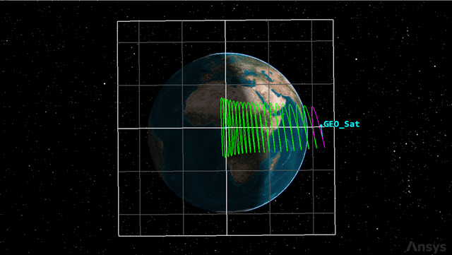
GEO_Sat drifts east
The satellite starts drifting eastward and its inclination starts changing over time. When the East border is reached, an east-west station-keeping maneuver is performed and the drift is reversed in the opposite direction.
GEO_Sat drifts west
The amount of Delta-V is targeted such that the turnaround occurs at 12.55 degrees longitude (the Western edge of the box).
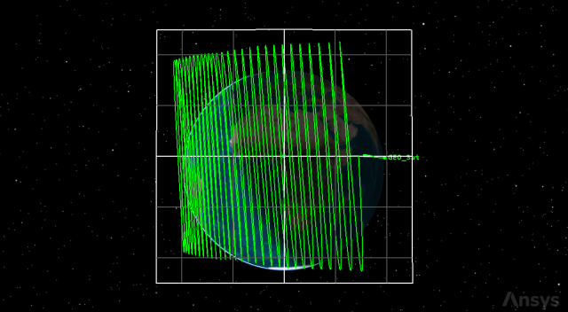
North-South Station-keeping Maneuver
Creating a custom TrueOfDate graph
The STK software includes a number of Geo Station Keeping data provider elements, which are useful for describing the motion of geosynchronous satellites, computed with respect to the Earth TrueOfDate system, as a function of time. Use two of these elements to create a graph to visualize the effects of the station-keeping maneuvers on its longitude and inclination.
Creating a new graph style
Create a custom style for your TrueOfDate graph.
- Right-click on GEO_Sat () in the Object Browser.
- Select Report & Graph Manager... (
 ) in the shortcut menu.
 - Select the My Styles () folder in the Styles panel of the Report & Graph Manager.
- Click Create new graph style (
 ) in the Styles panel toolbar.
 - Enter TrueOfDate Data.
- Select the Enter key.
Selecting the data provider elements
Use select Geo Station Keeping Elements to build your graph.
- Select the Content page when the Properties Browser opens.
- Expand () Geo Station Keeping Elements () in the Data Providers list.
- Select Geodetic Mean Longitude (
 ).
). - Click Insert Y Axis ().
- Select Inclination ().
- Click Insert Y2 Axis ().
- Click to accept your selections and to close the Properties Browser.
- Select TrueOf Date Data (
 ) in My Styles ().
 - Click .
This is the difference between the Mean Longitude, computed with respect to the Earth TrueOfDate axes, and the Mean Greenwich Hour Angle, which is the angle between the Earth Fixed X axis and the Earth TrueOfDate X axis. It is a measure of location in orbit relative to the Earth Fixed X axis, but still based upon time.
This is the angle between the orbit plane and the XY plane of the Earth TrueOfDate axes.
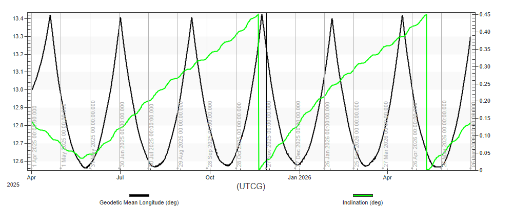
trueofdate data graph
Note the spikes in the longitude to when the satellite approaches the prescribed upper limit of 13.5 degrees, triggering the East-West station-keeping Automatic Sequence. The satellite's longitude curves down towards the limit of 12.55 degrees before increasing once again. Note also the satellite's inclination as it gradually rises towards the limit of 0.45 degrees. Reaching the limit triggers the North-South station-keeping Automatic Sequence, bringing the inclination down to the target value of 0 degrees.
Creating a Maneuver Summary report
Create a summary report for GEO_Sat's maneuvers.
- Return to the Report & Graph Manager.
- Select the Maneuver Summary (
 ) report in the Installed Styles () folder.
 - Click .
- Review the maneuver summary report.
You can see the differences between the station-keeping maneuvers. The East-West station-keeping burns last only fractions of a second to produce a small Delta-V. This requires comparatively little fuel. The North-South station-keeping maneuvers, however, require a much greater Delta-V. These burns last the greater part of a minute and use up a significant amount of fuel.
Saving your work
Clean up your workspace and save your work.
- Close any open reports, properties and tools.
- Save () your work.
Summary
You created a geostationary box that you used as a reference frame for a geostationary satellite, GEO_Sat. You propagated GEO_Sat, which showed a continuous eastern drift. Creating an Automatic Sequence, you constrained GEO_Sat's drift inside the geostationary box in an East-West direction. You created a second Automatic Sequence that constrained GEO_Sat's North-South drift inside the geostationary box. You ended by creating a custom graph illustrating Geo_Sat's East-West and North-South drift and a Maneuver Summary report that provided an overview of GEO_Sat's performance over time.