Part 1: Air to missile observations with STK EOIR capability
STK Premium (Air), STK Premium (Space), or STK Enterprise
You can obtain the necessary licenses for this tutorial by
Required Capability Install: For versions 12.10 and earlier of the STK software, this lesson requires the installation of the EOIR capability. For these versions of the software, the EOIR installer is included in the STK Premium software download, but requires a separate installation process. Read the Readme.htm found in the STK software install folder for installation instructions. You can obtain the necessary install by visiting https://support.agi.com/downloads or calling AGI support.
The results of the tutorial may vary depending on the user settings and data enabled (online operations, terrain server, dynamic Earth data, etc.). It is acceptable to have different results.
Capabilities covered
This lesson covers the following STK capabilities:
- STK Pro
- Electro-Optical Infrared Sensor Performance (EOIR)
Problem statement
To succeed in an upcoming mission, you need to determine when a system can detect, track, identify, and characterize targets of interest under operational conditions. You know that modeling and simulating these operations with a set of different tools can take far too long and is prone to mistakes. You need a single, physics-based, multi-domain analysis platform to accelerate your work.
Solution
This lesson will guide you through STK's EOIR capability at a basic level. You will model an observation system on an aircraft. You will track a missile and use EOIR to see what the camera on the aircraft would see. You will do this by generating an EOIR Synthetic Scene.
Once you complete this tutorial, you will be able to:
- Design an air-based observation system
- Build a mid-wavelength infrared camera
- Analyze synthetic scenes and data
For more information and to see other examples of EOIR, please check out the available topics on the Help Welcome page.
Video guidance
Watch the following video. Then follow the steps below, which incorporate the systems and missions you work on (sample inputs provided).
Define the scenario’s environment
You will be creating a new scenario.
-
Click the Create a Scenario (
 ) button.
 - Enter the following in the New Scenario Wizard:
- Click .
| Option | Value |
|---|---|
| Name | EOIR_AirObservations |
| Start Time | Default Start Time |
| Stop Time | + 0 .5 days |
Verifying that EOIR is installed
Ensure that EOIR is installed on your computer.
- If you do not see the EOIR toolbar (
 ), extend the View menu.
 - Select the Toolbars option
- Select EOIR.
Turning off terrain
In this analysis, you will not be utilizing the streaming terrain imagery. The missions will be in the air.
- Open EOIR_AirObservations's () properties.
- Select the Basic - Terrain page.
- Clear the Use Terrain Server for Analysis check box.
- Click .
Inserting an Aircraft object
Create the object the camera system will be placed on. For this setup, you will model a quick flight path and observe a missile from launch to impact.
- Insert a Aircraft (
 ) object using the Define Properties (
 ) method.
 - Set the following for the aircraft waypoints; leave the non-specific values as the default.
- Click to save your changes
|
Latitude |
Longitude |
Altitude |
Turn Radius |
|---|---|---|---|
|
33.00 deg |
-80.00 deg |
20.00 km |
1.00 km |
|
32.00 deg |
-77.00 deg |
20.00 km |
1.00 km |
Inserting a Missile object
The target object will be the missile. Set the following launch and impact points and leave all others as the default.
- Insert a Missile (
 ) object using the Define Properties () method.
 - Enter 30 deg in the Launch Latitude - Geodetic field.
- Enter -80 deg in the Launch Longitude field.
- Enter 35 deg in the Impact Latitude -Geodetic field.
- Enter -75 deg in the Impact Longitude field.
- Set the missile speed to 5 km/sec in the Delta V field.
- Click .
Specifying the Missile – EOIR Shape
Next, set up the EOIR Shape for the missile. This will define what the sensor will see when it targets the missile. You will create a generic missile, which is a cylinder with a cone on top.
- Go to the Basic – EOIR Shape.
- Set Component 1.
- Click next to the Component Panel.
- Set Component 2.
- Click to save your changes.
|
Option |
Value |
|---|---|
|
Shape |
Cylinder |
|
Height |
50 m |
| Radius | 10 m |
| Body Temperature | Static |
| Temperature | 500 K |
|
Option |
Value |
|---|---|
|
Shape |
Cone |
|
Height |
50 m |
| Radius | 10 m |
| Body Temperature | Static |
| Temperature | 500 K |
Specifying the Missile – EOIR Stage
The missile has a burn as it takes off. Take a look at the burn in the EOIR Stage tab for the missile.
- Go to the Basic – EOIR Stage.
- Examine time On Time Delta and Off Time Delta. By default, the missile burns for a minute. Let's change this parameter.
- Set the Off Time Delta to 30 sec.
- Click to save your changes.
Inserting a Sensor object
Bring a Sensor object into the scenario. This will be the camera that tracks and follows the missile. You will place the camera on the nose of the aircraft and track the missile.
- Insert a Sensor (
 ) object using the Insert Default method.
 - On the Select Object window, attach the sensor to the aircraft.
- Open the sensor's properties.
- Go to the Basic – Location and set the following values.
- Go to the Basic – Pointing.
- Click .
|
Option |
Value |
|---|---|
|
Type |
Fixed |
|
Fixed Location - Type |
Cartesian |
| X | 0.018 km |
| Y | 0 km |
| Z | 0 km |
|
Option |
Value |
|---|---|
|
Pointing Type |
Targeted |
|
Assigned Target |
Missile Object |
Specifying EOIR settings
Set the EOIR parameters for the sensor. We will work through each tab on the Basic-Definition page to define the system.
Setting the Sensor Type to EOIR
Model an EOIR sensor type with one band. EOIR supports up to 36 bands per sensor. You will have one band for our analysis.
- Select the Basic - Definition page.
- Set the Sensor Type to EOIR.
- Double-click in the Band name field.
- Rename the band MWIR. This is short for Mid-wave Infrared, which is the part of the spectrum you're analyzing.
EOIR Settings – Spatial
The Spatial tab contains the spatial information of the sensor. This is where you define the total field-of-view angles and the number of pixels on the sensor detector.
- Set the Field of View section on the Spatial tab:
- Leave the Number of Pixels as the default.
|
Option |
Value |
|---|---|
|
Vertical Half Angle |
0.02 deg |
|
Horizontal Half Angle |
0.02 deg |
EOIR Settings – Spectral
The Spectral tab is where you define the spectral range of your sensor. The sensor model samples your spectral band using the number of intervals you define. The more intervals you have, the higher the accuracy of the analysis. However, more intervals mean longer computation time.
- Select the Spectral tab.
- Set the Spectral Band Edge Wavelengths section as follows:
- Leave the Number of Intervals as the default.
|
Option |
Value |
|---|---|
|
High |
5.50 um |
|
Low |
3.00 um |
You must enter the High value before the low value to avoid errors.
EOIR Settings – Optical
- Select the Optical tab.
- Set the following values:
- Change the Image Quality to Negligible Aberrations.
- Leave the Optical Transmission and Diffraction Wavelength as the defaults.
|
Option |
Value |
|---|---|
| Input | Focal Length and Entrance Pupil Diameter |
|
Effective Focal Length |
415.00 cm |
|
Entrance Pupil Diameter |
100.00 cm |
The Image Quality property models wave front error through the optics. The Negligible Aberrations setting introduces 7% wave front error.
EOIR Settings – Radiometric
- Select the Radiometric tab
- Set the Input to High Level
- Set Sensitivity section values to:
- Leave all other parameters as the defaults.
- Click to save and close the properties.
|
Option |
Value |
|---|---|
|
Integration Time |
100 |
|
Equivalent Value |
1 e-15 |
Targeting the Missile object in EOIR
Once you’ve made your changes to the sensor, make sure it knows the behavior of the missile.
- Click the EOIR Target Configuration (
 ) button on the EOIR toolbar.
 - Highlight the Missile () object from the list in the Available STK Objects panel.
- Use the arrow button (
 ) to move the missile to the Selected Targets list.
 - Click .
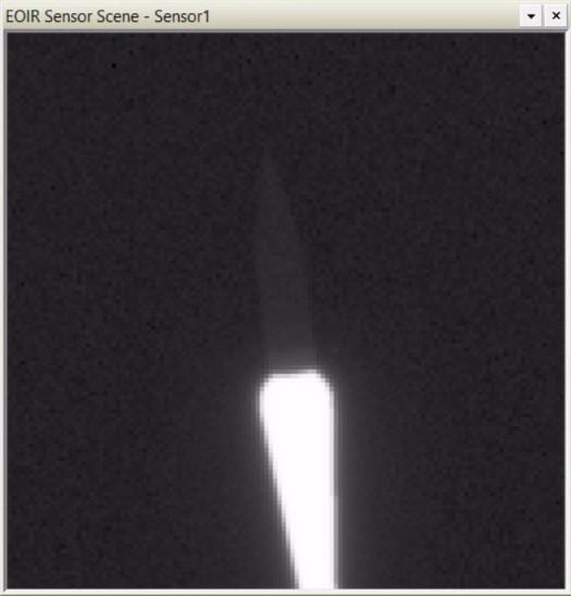
Generating the Synthetic Scene
The missile will launch from the ground, to make it easier to see move forward in the scenario by a few seconds.
- Select the sensor in the Object Browser
- Click the EOIR Synthetic Scene (
 ) button in the EOIR toolbar to generate an image that represents the sensor output.
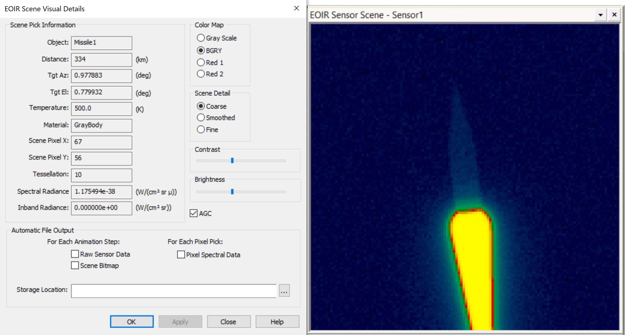
 - Right-click on the sensor scene and select Details....
- Using your mouse click in the scene to generate information about each point in the scene.
- Play around with the Color Map, take a look at the BGRY Color Map, and others
- Click .
- Close the EOIR Scene Visual Details properties page when you finish.
- Close the Synthetic Scene.
The data in each sensor click can be saved to a file by selecting Pixel Spectral Data on the EOIR Scene Visual Details page. For the Sensor Output processing level, the raw sensor data and image can be saved out at every animation step. These images can be compounded to create a movie or run through external image processing software for further analysis.
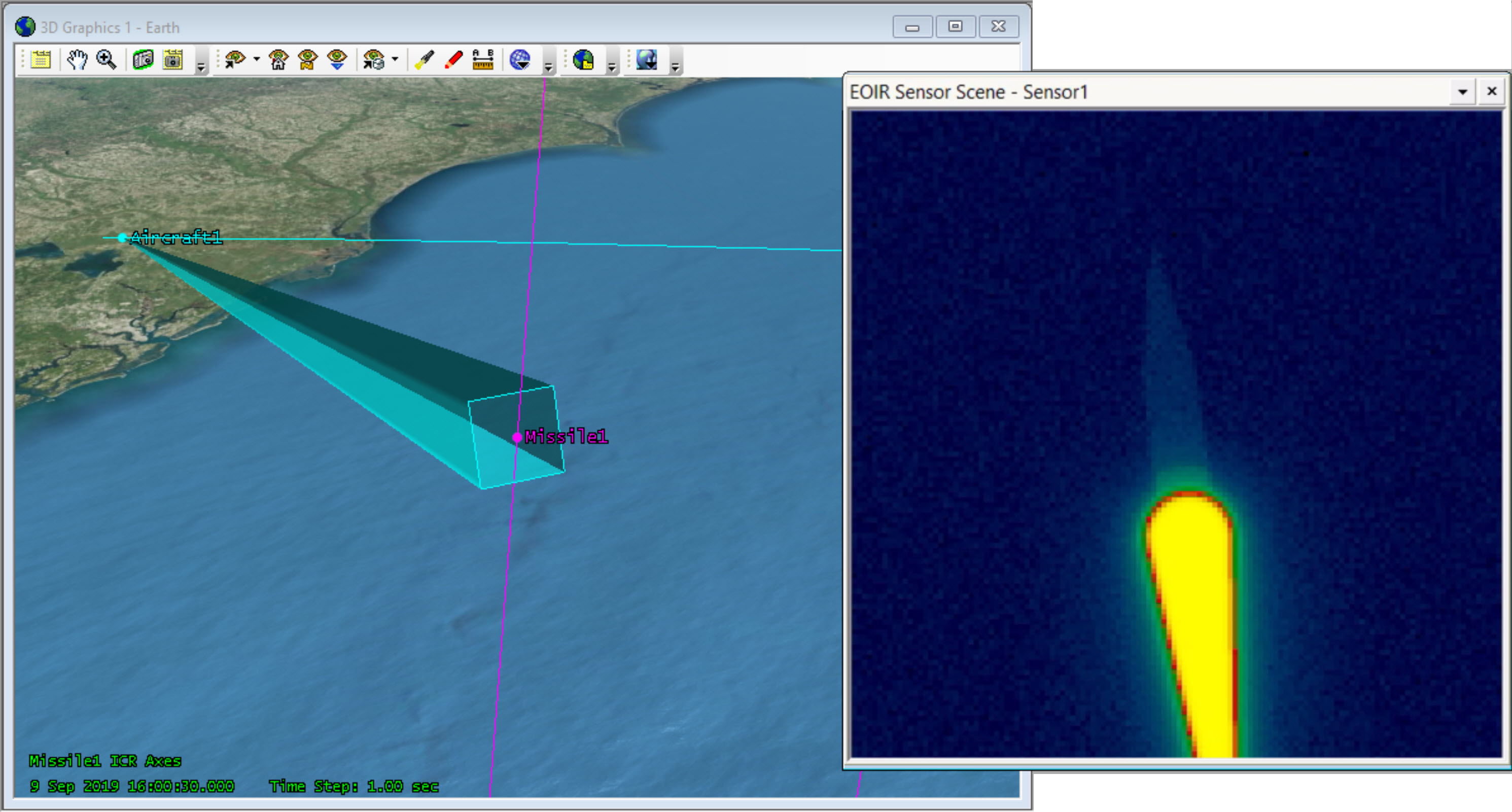
Examine an event
The Missile is burning for the first 30 seconds of launch. View what the sensor is seeing the moment before and after the burn ends.
- Manually change the scenario time so that it is 30 seconds after your scenario start time (for example: 16:00:30.000).
- Examine your scenario and you should see your missile mid-flight.
- Decrease the Time Step of your scenario so that it is set to 1 sec.
- Regenerate your EOIR Synthetic Scene by clicking the EOIR Synthetic Scene () button.
- Use the animation Step Forward button to go one step (1 sec) past the end of the burn time. Examine your Synthetic Scene and note the changes. At this new moment in time there is no burn, so the leveling for the noise in your synthetic scene will also update.
- Close the Synthetic Scene when you finish.
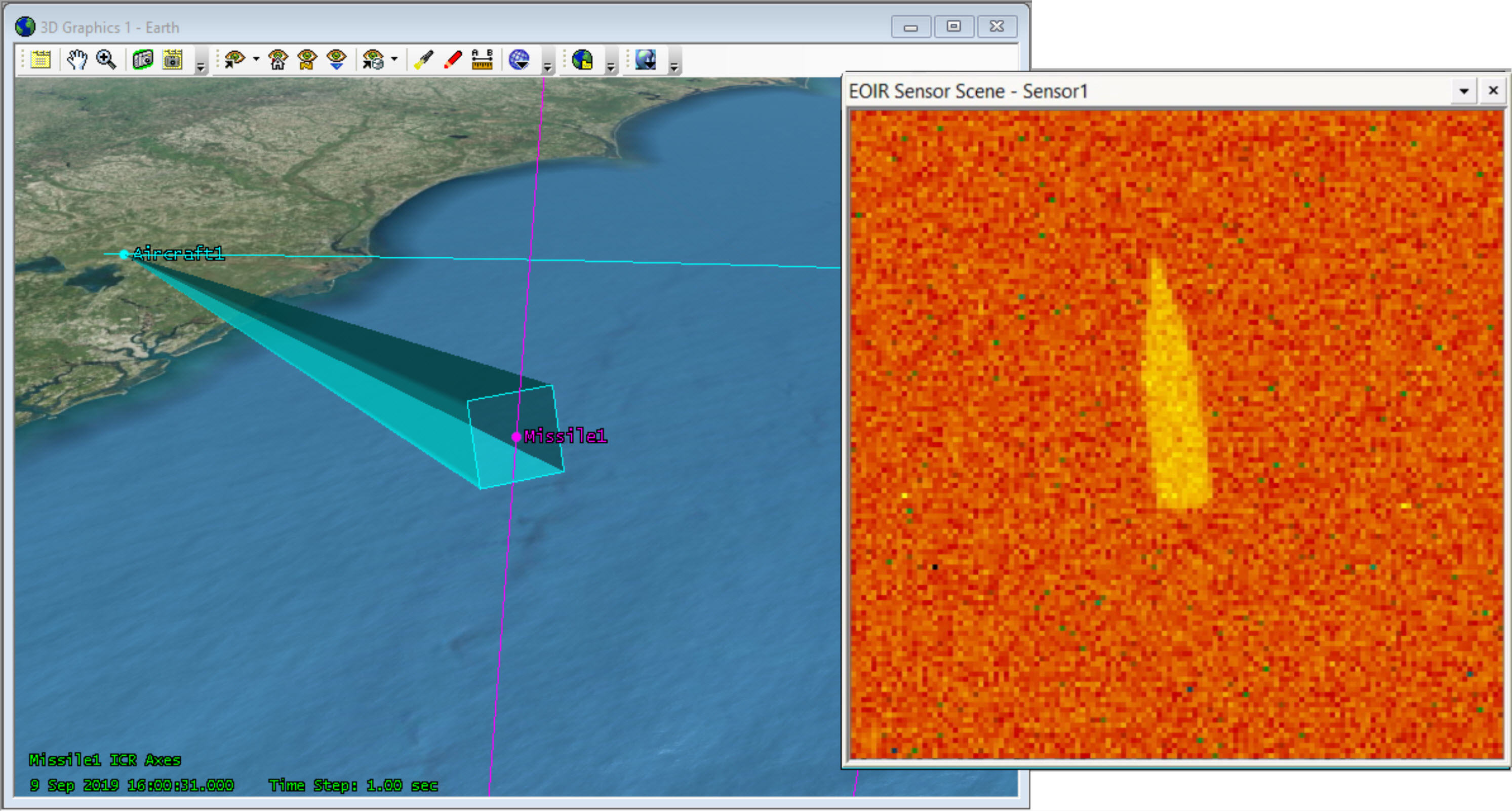
The image may vary based on the signal-to-noise ratio of the missile.
Playing around with the settings
Now that you’ve taken a look at the missile, see how the system is affected when the target changes or if we make changes to the system
- Go to Basic – EOIR Shape.
- Set the Temperature of Component 1 to 1000 K.
- Click .
- Take a look at the scene. How did changing the temperature affect the results?
The scene automatically regenerates if the image is open.
Changing the material
See how changing the missile material changes the EOIR synthetic scene.
- Go back to the Missile properties.
- Set the Temperature back to 500K.
- Set the Material to Aluminum MLI.
- Click . How did changing the material affect the results?
- Change the Material back to Gray Body.
- Click .
- Close the Synthetic Scene.
Generating data
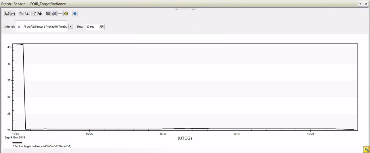
EOIR does more than simulate scenes created by an EO/IR sensor. It can also calculate metrics a sensor would receive from a target's signal. The following will familiarize you with some of the available EOIR data providers. Specifically, you will look at the Effective target radiance which measures the Power Flux Intensity. This is the average apparent radiance at the sensor aperture from a target object. Take a look at the information we get.
- Right-click the Sensor () and select Report & Graph Manager.
- Click the Create a New Graph Style (
 ) button to create a custom graph for the sensor.
 - Name the new graph EOIR_TargetRadiance.
- Open up the graph’s Content properties.
- Move () the Effective target radiance data element to the Y Axis in the EOIR Sensor to Target Metrics data provider.
- Click to finalize your custom graph and return to the Report & Graph Manager.
- Double-click on the newly created graph. It may take STK a moment to generate the data.
- Change the interval step size from the default time step to 10 sec.
- Take a look at your targets behavior. Do the results match the predicted behavior? Note when the missile burn turns off and how the radiance drops.
- Use the magnifying glass to examine the radiance values after the burn has ended.
Saving the Synthetic Scene information
Using Connect commands, you can quickly export data from their EOIR synthetic scene. Run the commands below to pull out data from this mission.
Open the API Demo Utility
- Select View on the menu bar.
- Select Web Browser.
- Click Browse (
 ) on the Web Browser toolbar.
 - Click Example HTML Utilities on the left.
- Browse to STK Automation > API Demo.
- Select the API Demo Utility.htm.
- Click .
Run the Connect command
The two commands you will run are to "SaveSceneImage" and "SaveSceneRawData". Refer to the help resources to find more information on these commands. You only have a single band in your mission (MWIR), however note that you can export data on multiple bands.
- Set your scenario time to an instance that you want to pull data from (for example: 16:00:30.000).
- Enter the lines below in the Code Sandbox. Change the file path to your scenario file path, or your preferred file path.
- Click to execute the command.
- Examine the files in your folder. They can be used for post processing or presentation.
EOIRDetails */Aircraft/Aircraft1/Sensor/Sensor1 SaveSceneImage "C:/<user specified file path>/output_image.bmp" MWIR
EOIRDetails */Aircraft/Aircraft1/Sensor/Sensor1 SaveSceneRawData "C:/<user specified file path>/output_image.txt" MWIR
Saving your work
- Close any open reports, properties, and the Report & Graph Manager.
- Save (
 ) your work.
Summary
In this tutorial, you demonstrated how to build and analyze an observation system on an aircraft. You tracked a missile using an EOIR sensor to see what a camera on the aircraft would see and even generated data on it. This is especially useful information because you can see from your radiance graph that the signal is high during the initial burn but drops once the burn completes. Your ability to track and detect objects like missiles depends on the sensors you design and build for your missions.
On your own
Expand your mission. In this lesson, you modeled a single sensor and a single band.EOIR gives you the flexibility to model multiple sensors and bands for your mission. Try it out and see how your results may differ when looking at different parts of the spectrum. Use this lesson as a guide to expand all you can do with EOIR.