STK Free , STK Pro, STK Premium (Air), STK Premium (Space), or STK Enterprise
You can obtain the necessary licenses for this tutorial
The results of the tutorial may vary depending on the user settings and data enabled (online operations, terrain server, dynamic Earth data, etc.). It is acceptable to have different results.
Capabilities covered
This lesson covers the following capability of the Ansys Systems Tool Kit® (STK®) digital mission engineering software:
- STK Pro
Problem statement
Engineers, as a rule, focus on technical accuracy more than aesthetics. If your audience is largely nontechnical, movies and visual aesthetics may be a powerful influence. You need to be able to create effective movies. The one question that you never want to hear is, "What was that?" Asking, "What was that?" means that the movie has failed to tell the intended story.
Solution
The STK application provides the capability to either save a collection of still frames from the 2D or 3D Graphics windows, and compile them into a movie with third party software, or save a ready-to-play movie directly from the STK application.
What you will learn
This tutorial covers preparation, camera control, and rendering content. In an ideal world, you would prepare your scene before positioning the camera, but sometimes you don’t realize something needs to be added, removed, or changed until after the camera has been positioned. So, in a real situation, you may find yourself switching back and forth between the first two steps.
Video guidance
Watch the following video. Then follow the steps below, which incorporate the systems and missions you work on (sample inputs provided).
Opening the starter scenario
A starter scenario has been provided for you and is included in the STK application installation.
- Launch the STK application (
 ).
). - Click
 Open a Scenario when the Welcome to STK dialog box opens.
 - Browse to <Install Dir>\Data\Resources\stktraining\VDFs.
- Select Models_And_Movies.vdf.
- Click .
If you are using an older version of the STK application, browse to <Install Dir>\Data\ExampleScenarios and open Intro_STK_Space_Systems.vdf.
Saving the VDF as a Scenario file
When you open the VDF, the STK application creates a folder with the same name as the scenario in the default user folder. The STK application does not automatically save the scenario. When you save a scenario in the STK application, it saves in the format in which it originated. Therefore, if you open a VDF, the default save format is a VDF. The same is true for a scenario file (*.sc). To save the VDF as a *.sc file, change the file format using the Save As procedure below.
- Open the File menu.
- Select Save As... .
- Select the STK User folder in the navigation pane.
- Select the Models_And_Movies scenario folder.
- Click .
- Open the Save as Type drop-down list.
- Select Scenario Files (*.sc).
- Click .
- Click to confirm.
Save (![]() ) your scenario often!
) your scenario often!
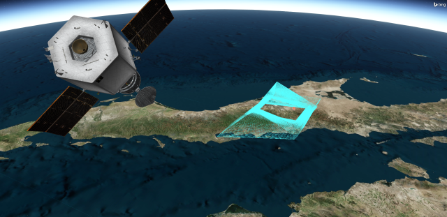
The mission in this example is a Low Earth Orbiting (LEO) satellite that collects imagery of ground targets. It then downlinks the data to multiple ground stations while maximizing power to the satellite’s solar panels. The satellite’s orbit line is colored based on the intervals for payload imaging, antenna downlink, sunlight, penumbra, and umbra.
You will be making updates in the main 3D Graphics window.
Changing the scenario's units
Optimizing visualization for movie making sometimes requires that you perform some simple calculations to determine your optimal bit rate and time step. Model articulations also reference times, such as their start, stop and duration, in epoch seconds. That being the case, it’s always good practice to change the date format to epoch seconds when using a scenario for movie making.
- Right-click on Models_and_Movies (
 ) in the Object Browser.
 - Select Properties (
 ) in the shortcut menu.
 - Select the Basic - Units page when the Properties Browser opens.
- Select DateFormat in the Dimension List.
- Click Gregorian UTC (UTCG) in the CurrentUnit list.
- Open the drop-down list.
- Select Epoch Seconds (EpSec).
- Click the Enter key.
- Click to confirm your selection and to close the Properties Browser.
Making effective movies
A movie, for the purpose of this discussion, is a single scene of continuous motion. A movie may run from a few seconds to a few minutes, depending on your requirements. Movies tell a story. The story can be about something that has happened, might happen, or something that is happening right now. Scenarios in the STK application do the same thing, but often cover a much larger area in both time and space than a single movie can convey.
Movie making can be divided into three parts:
- Preparing the scene
- Controlling the camera
- Rendering the content
This tutorial assumes that your scenario is technically complete. Preparing the scene, which comes next, is what you do to make it movie ready.
Preparing the scene
There are three areas that comprise scene preparation:
- Adjusting the lighting
- Adjusting the framing
- Adjusting the visual elements
Adjusting the lighting parameters
Lighting parameters are on the 3D Graphics - Lighting page of the 3D Graphics window properties. For a complete description of the lighting panel, see Lighting Properties for the 3D Graphics Window. The STK application's default lighting source is the Sun. To ensure good contrast, you will update the sun lighting.
Adjusting the Sun lighting
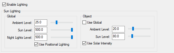
There are two settings for Sun Lighting: Global and Object. Global Lighting only affects how the sun lights the central body. Object Lighting only affects objects that are part of your scenario. This includes clouds and sensors.
The Ambient Level determines how bright the darkest parts of your globe or objects will be lit. To increase contrast, lower Ambient Level while increasing the Sun Level. Maximizing Global Sun and Night Lights levels (setting them to 500) optimizes the sharpness of the solar terminator.
Under Object, the Ambient Level plus Sun Level should always equal 100. If it does not, objects in your scenario will appear either overexposed or underexposed.
- Click the 3D Graphics window in the Integrated Workspace to bring it to the front.
- Right-click in the 3D Graphics window.
- Select Properties... () in the shortcut menu.
- Select the Lighting page.
- Set the following in the Global panel of the Sun Lighting panel:
- Set the following in the Object panel of the Sun Lighting panel:
- Click to confirm your changes and to keep the Properties Browser open.
| Option | Value |
|---|---|
| Ambient Level | 20.0 |
| Sun Level | 500.0 |
| Night Lights Level | 500.0 |
| Option | Value |
|---|---|
| Ambient Level | 20.0 |
| Sun Level | 80.0 |
Lighting options
Adding a flashlight
What if your movie starts out on the dark side of the Earth? Try not to let this happen. If your movie must start on the dark side, you can add lighting sources. A less precise, but much faster, solution is to use the flashlight.
- Select the Show check box in the Flashlight panel..
- Click to confirm your change and to keep the Properties Browser open.
Adjusting the framing
Framing has to do with the shape and size of your video and the volume of space it contains. You can divide framing into two parts:
- Screen size
- Field of view
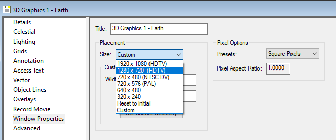
Selecting a screen size
Screen size is on the Window Properties page of the 3D Graphics window properties. You can choose one of the predefined window sizes from the drop-down menu, or you can define a custom window size. For desktop presentations, use 1280 x 720 (HDTV).
- Select the Window Properties page.
- Open the Size drop-down list in the Placement panel.
- Select 1280 x 720 (HDTV).
- Click to confirm your change and to keep the Properties Browser open.
Window Properties
Viewing changes in the 3D Graphics window
You will restore the 3D Graphics window to normal size.
- Bring the 3D Graphics window to the front.
- Click Restore the window to normal size (
 ).
).
The 3D Graphics window resizes to 1280 × 720 px.
Changing the field of view
The field of view defines how much you can see, in degrees, in the 3D Graphics window. As your field of view gets wider, the objects in your 3D Graphics window get smaller, but you will also see more of them. The maximum angle is 160 degrees.
The STK application's default value for the field of view is 45 degrees. A square 3D Graphics window has the same field of view in both directions. If the 3D Graphics window is 1280 pixels wide and 720 pixels high, only the largest dimension, in this case 1280, matches the field-of-view setting. 70 degrees is a good starting point for movie making.
- Return to the 3D Graphics window's Properties.
- Select the Advanced page.
- Enter 70 deg in the Field of View field in the Viewing panel.
- Click to confirm your changes and to close the Properties Browser.
- Save (
 ) your work.
Adjusting the visual elements
Visual elements of a movie include models, textures, and terrain. Some elements may move and change; others won't. Visual elements may have little to do with the technical nature of your scenario, but often add credibility to the technical parts that are already there. Depending on their size and frequency of use, some of these may impact performance.
Managing terrain, imagery, and globes
You are going to be recording your video zoomed in to the satellite, while it is in the sunlight. If you need to make globe enhancements or add terrain, you can do that in the Globe Manager. To enhance your 3D Graphics window, you can add a high-resolution Nightlights texture, animated water surfaces, a global specular highlight, and world cloud textures. Some of these visual elements are included in the STK application install and the rest are on the
Removing objects from the 3D Graphics window
To clean up the scenario, if there are objects in your scenario that you do not need for the movie, you can either delete them from the scenario or toggle them off in the Object Browser.
- Clear the SunSensor (
 ) check box in the Object Browser.
 - Clear the SunSensorTrue () check box in the Object Browser.
Enhancing labels and annotations
Here are a few suggestions to improve the appearance of labels, annotations, and lines:
- Remove any unnecessary labels and lines in your 3D Graphics window. Open the object's Properties () and go to the 2D Graphics - Attributes page. Select the Basic option. Under Inheritable Settings, clear the Inherit from Scenario check box. Then you can clear any or all of check boxes such as label, orbit line, ground track, etc.
- Remove any unnecessary annotations in your 3D Graphics window. To disable annotations, click the 3D Graphics window properties () icon and go to the Annotation page. There you can clear any check boxes for annotations related to time, viewer position, reference frame, etc.
- Set your scenario so that LEO-to-target access lines do not appear in the movie. Right-click the Models_and_Movies scenario, open Properties (), and select 2D Graphics - Global Attributes. Under Access, clear the Show Animate Line check box.
- Labels and annotations look best in plain, thick font. Thin or small font is difficult to read in a video. You can adjust the fonts under the Scenario Properties in the 3D Graphics - Fonts page.
Clearing LEO's vectors and axes
Clear the display of the vectors and axes from the 3D Graphics window.
- Open LEO's (
 ) Properties ().
 - Select the 3D Graphics - Vector page.
- Select the Vectors tab.
- Clear the Sun Vector - Show check box.
- Select the Axes tab.
- Clear the Body Axes - Show and VVLH Axes - Show check boxes.
- Click to confirm your changes and to keep the Properties Browser open.
Using 3D models
You can use 3D models to represent scenario objects and aid in analyzing and visualizing the relationships among the objects. The STK application contains detailed 3D models representing objects such as ground stations, aircraft, air strips, satellites, aircraft carriers, and helicopters. Once you specify a model to represent an object, it is graphically displayed in its position and orientation as defined in the object's Basic properties. The STK application places the center of a model at the X, Y, and Z position of the object it is representing. Position and orientation can vary over time, and you can manually adjust them within the object's 3D Graphics properties. Supported model file types are:
- glTF models (.glb)
- MDL models (.mdl)
Support for 3D models using the COLLADA (.dae) format has been deprecated. COLLADA models used in legacy STK scenarios should be converted to the gLTF model format, using any of the readily available 3D modeling content creation tools such as Blender, Maya, or Modo
Modifying or creating models
You may need to modify or create a model file if you:
- Work in a classified environment
- Need to add an attach point or an articulation
- Require a new design
Once you have a model, you can add functionality. Ancillary features consist of articulations (moveable components), attach points, pointable elements, and solar panel groups.
Looking at LEO's model's properties
A model articulation defines a range of positions and orientations for a component or primitive, such as the allowable gimbal angles for an antenna. Articulations do not change the way an STK object is defined, and they do not affect access or other calculations between objects being modeled. Use it to visually resolve anomalies or to provide realistic motion in the models for animation.
You can edit articulations in a few ways:
- In the Object's Properties, on the 3D Graphics - Model page
- Manually, in the Movie Timeline Tool
- In the articulations file
Viewing LEO's model articulations by viewing its properties
- Return to LEO's () Properties ().
- Select the 3D Graphics - Model page.
- In the Model File field, notice it is using voyeur_4.mdl.
- Click in the Articulations panel.
- Note the available articulations in the Articulations list.
- Select Voyeur in the Articulations panel.
- Click to close the Model Articulations dialog box.
- Make sure that Use Articulation File is selected, and the file is LEO.sama.
- Click to close the Properties Browser without making any changes.
This opens the Model Articulations dialog box which allows you to view the available articulations for this model.
This allows you to view, if any, transformations in the Transformations panel. The slider to the right of the transformations allows you to view the upper and lower values of the transformation.
When you create your movie, you will see that this file is telling the model when to open the Imaging Barrel Door and when to close it.
Exploring the articulation file
This scenario is using an articulation file that is automating the execution of moving parts at the appropriate time. It contains the information needed to animate the articulation commands contained in the model file. The model articulation file contains a time-ordered list of data about each articulation that can be applied to the associated object.
- Open Windows Notepad or a text editor of your choice.
- Open the File menu.
- Select Open....
- Open the Text Documents (*.txt) drop-down list.
- Select All Files.
- Go to the scenario folder (e.g., C:\Users\<username>\Documents\STK_ODTK 13\Models_and_Movies).
- Select LEO.sama.
- Click .
- Note the last two articulations in the file.
- Close Notepad.
This file defines when to articulate (in this case, open and close) Imaging_Barrel_Door and the duration of the articulations. When you create your movie, you will see that the door is opening before the first image collection and remains open during the image collection.
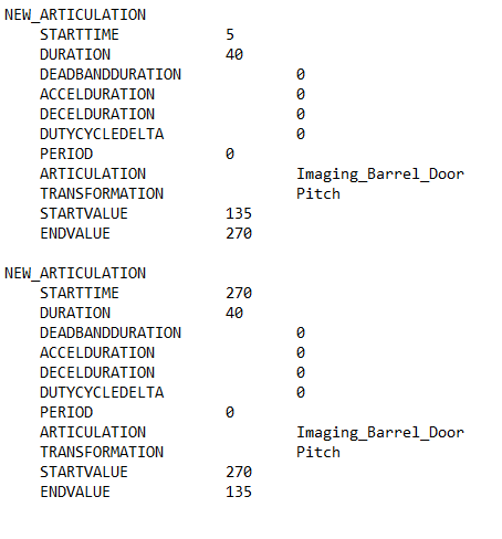
LEO.sama articulation file contents
Viewing the articulations in the 3D Graphics window
View the animated articulation in the 3D Graphics window.
- Bring the 3D Graphics window to the front.
- Click Start (
 ) in the Animation toolbar to animate the scenario.
 - Watch the Image Barrel Door open, and then watch it close.
- Click Reset (
 ) on the Animation toolbar when you are finished.
Creating the video
You are now ready to make your movie. Use the
- Keyframes property page: Use this page to add, modify, copy, and delete camera paths. Many of the functions on this screen are duplicated on the Camera Control toolbar.
- 3D Window Properties page: Use this page to define camera control properties of a particular 3D Graphics window.
- Render Properties page: Use this page to control how the camera paths are drawn in the 3D Graphics window.
- Camera Control toolbar: Use this toolbar to interact with camera paths.
Opening the camera control tool
Display the 3D Camera Control toolbar and open the Camera Control tool.
- Open the View menu.
- Select Toolbars.
- Select 3D Camera Control in the Toolbars submenu.
- Click Camera Control (
 ) to open the Camera Control tool.
Creating a camera path
To create a camera path, the STK application stores a series of keyframes at intervals along the desired path. The Camera Control tool uses these keyframes to build a smooth line using a splining algorithm. When you create a viewpath, you place these keyframes so that the desired regions of interest are in the camera’s view at the appropriate times.
There are many ways to go about making a great camera path, but nearly all of them share certain characteristics:
- Avoid crowds: Make sure each keyframe evenly fills the 3D window as much as possible. Avoid bunching relevant action into one area and leaving wasted space elsewhere. This happens a lot to object labels. Remove any nonessential labels. Labels must always be legible.
- Stay focused: Keep relevant action near the center of the frame as much as possible. If the relevant action goes out of frame between keyframes, pause your scenario and add a new keyframe where this happens. If you want to change a keyframe, double-click on the keyframe, reposition the camera, and overwrite the keyframe with your new camera position by clicking . The viewer position, direction, and time will change to that of the selected keyframe. In each scene that you record, there should be a single “money shot” that depicts the essence of what you wish to convey.
- Keep moving: Once the camera is moving in a given direction, keep it moving in that direction. If you run out of room, start sooner, but never reverse direction. Home movies are famous for this. The camera looks like it’s attached to a windshield wiper. This conveys confusion and a lack of confidence to the viewer. If you must move in the opposite direction, start by moving diagonally, then at a right angle, opposite diagonal, and finally opposite. Move like an ice skater.
- Mind the gap: Keep keyframes evenly spaced. When there is a profound change in camera location or direction, users experience unpredictable camera motion between keyframes. If you are lucky, this may work for you.
- Less is more: The fewer keyframes you have, the smoother your camera path will be. Each keyframe produces a change in the spline. If you have too many keyframes, your path will appear bumpy. Delete keyframes that don't contribute. Add keyframes between other keyframes to stay focused.
Setting the animation start time of your scenario to the desired movie start time
There are many ways to set the start and stop times of a video. The following is a quick and simple way to do this.
- Open the Models_and_Movies' () Properties ().
- Select the Basic - Time page when the Properties Browser opens.
- Open the Start Time drop-down list in the Animation panel.
- Select Start Time in the shortcut menu.
- Select Replace With Time in the second shortcut menu.
- Enter 5.0 EpSec in the Start Time field.
This is when the Imaging Barrel Door begins to open.
Setting the animation stop time of your scenario to the desired movie stop time
- Select the check box to the left of Stop at Time in the Animation panel.
- Open the Stop at Time drop-down list.
- Select StopTime in the shortcut menu.
- Select Replace With Time in the second shortcut menu.
- Enter 315 EpSec in the Stop at Time field.
This is approximately five (5) epoch seconds after the Imaging Barrel Door finishes closing.
Adjusting the step size to a non-default value
When you increase or decrease the time step using the Animation toolbar, the STK application uses default step sizes. You can set a non-default step size in the Animation panel of the Scenario object's properties.
- Enter 0.2 sec in the Step Size field in the Animation panel.
- Click to confirm your changes and to close the Properties Browser.
- Click Reset (
 ) in the Animation toolbar.
The scenario resets to the time you want the movie to begin.
Creating the starting keyframe
The safest way to produce a camera path is to establish starting and ending keyframes. The beginning of your movie often familiarizes viewers with the context of your scenario. It is called an establishing shot. For this keyframe, you almost always want to position the camera some distance away. It is good to have balance in the keyframe. For example, have action on the left and action on the right. Try to make the keyframes at points where you really want the camera to show the very best visuals that you can arrange. It is good to try to capture some dramatic lighting or show a feature of Earth.
- Bring the 3D Graphics window to the front.
- Right-click on LEO () in the Object Browser.
- Select Zoom To in the shortcut menu.
- Zoom to LEO and reposition the view in the 3D Graphics window so there is balance on the screen.
For example, LEO is zoomed in on the left and the target is in view on the right while still seeing the horizon.
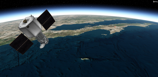
LEO and target, well-framed
Creating a camera path
A camera path is made up of a sequence of Keyframes.
- Bring the Camera Control tool to the front.
- Select the Keyframes page.
- Click in the Camera Path panel.
- Rename the camera path LEO_Image.
This will add a new camera path segment to the table.
Creating a keyframe
A keyframe stores the viewer position, orientation and time.
- Click .in the Keyframes panel.
This will use the current scenario time to create the first keyframe.
Creating the ending keyframe
Now, create your last keyframe.
- Change the animation time to the end of the movie (315.0 EpSec).
- Bring the 3D Graphics window to the front.
- Use the mouse to manipulate the view to balance the action in the 3D Graphics window. You can recenter your object if needed, then make the adjustments. Make sure you capture the action you want to see, such as LEO flying away from the Target on the ground.
- Return to the Camera Control tool.
- Click in the Keyframes panel.
- Click to confirm your changes and to keep the Camera Control tool open.
LEO targeting ground
This will add a second keyframe to your camera path.
Animating the scenario by following the camera path
Set your animation to follow the camera path.
- Double-click on Keyframe 1 to return to the beginning of the Camera Path.
- Select the 3D Graphics window to make it active.
- Click the Follow Path While Animating (
 ) drop-down list the 3D Camera Control toolbar.
 - Select LEO_Image.
- Click Start () in the Animation toolbar to animate the scenario.
- Click Reset () when finished.
You should now see a box around the Follow Path While Animating (![]() ).
).
The path is from two keyframes; therefore it is a straight line rather than a spline. You need a third point to create the spline.
Adding a middle keyframe
It is likely the camera will be pointing the wrong way or looking at the wrong thing. Move the camera to where you want it to be at this time.
- Set the animation time to the halfway point of the movie (about 157.0 EpSec).
- Use the mouse to manipulate the view to balance the action in the 3D Graphics window.
- Return to the Camera Control tool.
- Select the first keyframe in Keyframes panel.
- Click in the Keyframes panel.
- Click to confirm your change and to keep the Camera Control tool open.
- Double-click on Keyframe 1 to return to the beginning of the camera path.
Viewing the spline in the 3D Graphics window
- Return to the 3D Graphics window.
- Click the Follow Path While Animating () drop-down list the 3D Camera Control toolbar.
- Select LEO_Image.
- Click Start () in the Animation toolbar to animate the scenario.
- Click Reset () when finished.
- Click to accept your changes and to close the Camera Control tool when finished.
You can keep going to a time between keyframes to make your camera follows the path you want, but know that the fewer keyframes you have, the smoother your path will be. Try to maintain a consistent amount of time and a consistent amount of change between keyframes. Change, in this case, relates to camera position and direction.
Rendering the content
Rendering is the final step in making a movie.
Setting the recoding options
The
- In the 3D Camera Control toolbar, ensure the Follow Path While Animating () option is active.
- Right-click in the 3D Graphics window.
- Select Properties... () in the shortcut menu.
- Select the Record Movie page.
- Select the Record every Animation Time Step option.
- Click the Directory ellipsis in the Output Options panel.
- Choose the Directory where you want to save the movie, usually in the scenario folder location.
- Enter the name of your movie in the File Name Prefix field.
- Open the Anti-Aliasing drop-down list in the Presentation Options panel.
- Select option 3x3.
- Click to confirm your changes and to keep the Properties Browser open.
By default, the Off option is active. Recording is disabled.
Even if you save the scenario with one of the Record buttons active, the STK application will always save the scenario with the Off option selected.
If you get an invalid path message, click .
With this option set, every frame that appears in the 3D Graphics window is saved to the computer's hard drive. This continues until you select the Off option and click .
Recording the movie
With everything now set, record your movie.
- Bring the 3D Graphics window to the front.
- Click Start () in the Animation toolbar to animate and record your scenario.
- When the animation stops, return to the 3D Graphics window Properties - Record Movie page.
- Select the Off option.
- Click to stop the recording and to close the Properties Browser.
The STK application will begin either writing still frames or compiling a movie file to your hard drive. It does not control the camera. The scenario will stop when the desired movie end time is reached, since that was set in the Scenario Properties. The STK application records the 3D Graphics window even If no camera path is activated. Recording continues until you reach the Stop Time of your scenario or you press pause (![]() ).
).
Viewing the movie
You can now view your movie.
- Bring Windows File Explorer to the front.
- Go to the directory where you saved the movie.
- Double-click on the movie file to play your movie.
Resetting the analysis time period
Reset your scenario’s analysis period once you are finished recording.
- Open Models_and_Movies' () Properties ().
- In the Animation panel, set the following options:
- Click to confirm your changes and to close the Properties Browser.
- Click Reset () in the Animation toolbar.
| Option | Value |
|---|---|
| Use Analysis Start Time | Selected |
| Use Analysis Stop Time | Selected |
Saving your work
Close out your scenario and save your work.
- Close any open properties and tools.
- Save () your work.
Summary
You started by cleaning and adjusting the view in the 3D Graphics window. You determined the start and stop times of your movie based on the articulations you wanted to see in the movie. You turned on the 3D Camera Control toolbar and opened the Camera Control tool. You created a camera path. Next you created a keyframe at the time you wanted to begin your movie and then created a second keyframe when the movie was complete, positioning the LEO satellite in the 3D Graphics window. You added a spline keyframe in between the start and stop keyframe to show more detail in the movie. You enabled the Follow Path While Animating feature in the 3D Camera Control toolbar. You then used the Record Movie page in the 3D Graphics window properties to record the move. When finished, you turned off the recording process and viewed the movie.