STK Premium (Space) or STK Enterprise
You can obtain the necessary licenses for this tutorial by
The results of the tutorial may vary depending on the user settings and data enabled (online operations, terrain server, dynamic Earth data, etc.). It is acceptable to have different results.
Capabilities covered
This lesson covers the following capabilities of the Ansys Systems Tool Kit® (STK®) digital mission engineering software:
- STK Pro
- Astrogator
- STK SatPro
Problem statement
Engineers want to model a mission to the Moon. They decide to use the method of B-plane Targeting to utilize the gravity assist to achieve the desired orbit. The B-plane is defined to contain the focus of an idealized two-body trajectory that is assumed to be a hyperbola.
Solution
Use the STK/Astrogator® capability to build a mission to the Moon. Starting from a parking orbit around the Earth, you will perform a trans-lunar injection to target the lunar B-plane. You will adjust the size of the maneuver to perform a lunar orbit insertion (LOI) to achieve a final circular lunar orbit with an inclination of 90 degrees.
This is an advanced Astrogator exercise, which presupposes familiarity with the STK software and some previous exposure to Astrogator. If you are new to the STK software, it is recommended that you first work through the STK Beginner training, which gives you a tour of the STK user interface and basic functionality of the STK application. For an entry-level introduction to Astrogator, try the exercise in which you use the targeter to model a Hohmann transfer.
What you will learn
Upon completion of this tutorial, you will be able to:
- Customize the graphics settings for multiple central bodies
- Set a targeter to target on the B-plane
- Model a lunar orbit insertion
Video guidance
Watch the following video. Then follow the steps below, which incorporate the systems and missions you work on (sample inputs provided).
Creating a new scenario
First, you must create a new STK scenario, and then build from there. You will define a scenario with a satellite and three planet objects—Sun, Earth and Moon—set up your 2D Graphics window to give an overview of the mission, and define two 3D Graphics windows providing Earth- and Moon-centered views of the mission.
- Launch the STK application (
 ).
). - Click
 Create a Scenario in the Welcome to STK dialog box.
 - Enter the following in the STK: New Scenario Wizard:
- Click when you finish.
- Click Save (
 ) when the scenario loads. The STK software creates a folder with the same name as your scenario for you.
 - Verify the scenario name and location in the Save As dialog box.
- Click .
| Option | Value |
|---|---|
| Name | LunarMission |
| Location | Default |
| Start | 1 Jan 2025 00:00:00.00 |
| Stop | + 30 days |
Save (![]() ) often during this lesson!
) often during this lesson!
Preparing the scenario
Make some changes to your work space and the scenario properties.
- Close the Timeline View to free up more space for other windows.
- Close the 2D Graphics window.
- Right-click on LunarMission () in the Object Browser.
- Select Properties (
 ) in the shortcut menu.
 - Select the Basic - Time page in the Properties Browser.
- Enter 3 min in the Animation - Step Size field.
- Click to accept your selection and to keep the Properties Browser open.
Setting 2D and 3D Graphics attributes for space situational awareness
2D Graphics attributes at the scenario and local levels enable you to select what to view and how to view it in the 2D and 3D Graphics windows.
- Select the 2D Graphics - Global Attributes page.
- Set the following parameters:
- Click to accept your changes and to close the Properties Browser.
| panel | Option | Value |
|---|---|---|
| Vehicles | Show Orbits/ Trajectories | On |
| Show Orbit Markers | On | |
| All other selections | Cleared | |
| Planets | Show Orbits | On |
| Show Inertial Positions | On | |
| Show Position Labels | On | |
| All other selections | Cleared |
Adding the Planet object to the Insert STK Objects Tool
The
- Bring the Insert STK Objects tool to the front.
- Click .
- Select Planet in the New Object list in the Preferences dialog box.
- Click to accept your selection and to close the Preferences dialog box.
Inserting Planet objects into the scenario
The Planet object models orbital and other properties of a planet, a moon, an asteroid or the Sun.
- Return to the Insert STK Objects tool.
- Select Planet (
 ) in the Select An Object To Be Inserted list.
 - Select Insert Default () in the Select a Method list.
- Click three times.
Defining the planets' central bodies
The properties on the Planet object's Definition page enable you to identify the ephemeris source for each planet.
Adding the Sun to the scenario
Start by adding the Sun to your scenario.
- Open Planet1's () Properties ().
- Select the Basic - Definition page.
- Ensure Sun (the default selection) is the Central Body selection.
- Click to accept your selection and to close the Properties Browser.
Adding the Earth to the scenario
Now, add the Earth to your scenario.
- Open Planet2's () Properties ().
- Select the Basic - Definition page.
- Open the Central Body drop-down list.
- Select Earth.
- Click to accept your selection and to close the Properties Browser.
Adding the Moon to the scenario
Next, add the Moon.
- Open Planet3's () Properties ().
- Select the Basic - Definition page.
- Open the Central Body drop-down list.
- Select Moon.
- Click to accept your selection and to close the Properties Browser.
Enabling the ECI Coordinates grid in the 3D Graphics window
For ECI Coordinates, the space grid is displayed along the equatorial plane in the Earth-Centered inertial (ECI) coordinate system.
- Bring the 3D Graphics window to the front.
- Click Properties () on the 3D Graphics window toolbar.
- Select the Grids page in the Properties Browser.
- Select Show in the Space Grid - ECI Coordinates panel.
- Click to accept your change and to keep the Properties Browser open.
While on this page, you may want to select a relatively muted color for the grid (such as gray or olive green) so that it does not display in a prominent way in the 3D Graphics windows. Otherwise, it may detract from more important objects, such as orbit paths and the B-plane.
Renaming the 3D Graphics window
Rename the 3D Graphics for clarity.
- Select the Window Properties page.
- Enter Earth-Centered in the Title field.
- Click to accept your change and to keep the Properties Browser open.
Setting the maximum visible distance
Specify the maximum viewing distance in meters. The default is 10 million meters.
- Select the Advanced page.
- Enter 1e+010 km in the Max Visible Distance field in the Viewing panel.
- Click to accept your changes and to close the Properties Browser.
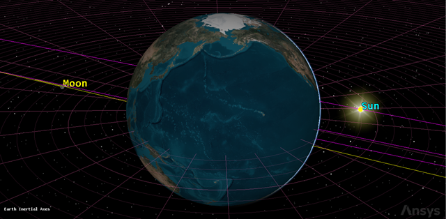
earth centered
Inserting a duplicate 3D Graphics window
You will insert a duplicate 3D Graphics window and center it on the Moon.
- Open the View menu at the top of the STK application.
- Select the Duplicate 3D Graphics Window submenu.
- Select Earth-Centered in the Duplicate 3D Graphics Window submenu.
Renaming the 3D Graphics window
Rename the 3D Graphics for clarity.
- Bring the 3D Graphics 2 - Earth window to the front.
- Click Properties () in the 3D Graphics 2 - Earth window toolbar.
- Select the Window Properties page.
- Enter Moon-Centered in the Title field.
- Click to accept your changes and to close the Properties Browser.
Changing the 3D Graphics window's Central Body
Change the central body of the Moon-Centered window.
- Open the Central Body (
 ) drop-down list in the 3D Graphics window toolbar.
 - Select Moon.
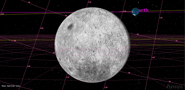
Moon centered
Inserting a Satellite object
The Satellite object models the properties and behavior of a vehicle in orbit around a central body.
- Insert a Satellite (
 ) object using the Insert Default () method.
 - Right-click on Satellite1 () in the Object Browser.
- Select Rename in the shortcut menu.
- Rename Satellite1 () to LunarProbe.
Propagating the Satellite object using Astrogator
The Astrogator capability contains specialized analysis for interactive orbit maneuver and spacecraft trajectory design. Astrogator calculates the satellite's ephemeris by running a Mission Control Sequence, or MCS, that you define according to the requirements of your mission.
Astrogator enables you to model impulsive and finite maneuvers as well as high-fidelity orbit propagation. It provides targeting methods, including:
- A differential corrector used to find the necessary values of control parameters (such as launch epoch or burn duration) to meet desired mission goals
- An optimizer used to change control parameters to achieve a goal, while applying a set of constraints that define the problem space
Furthermore, Astrogator allows you to define automatic sequences. These represent predefined sets of actions that can be performed whenever a specified event occurs, such as a maneuver that occurs at every periapsis. These details highlight just some of Astrogator's many features.
Astrogator also utilizes a component catalog and editor in the STK application called the Component Browser. The
- Open LunarProbe's () Properties ().
- Select the Basic - Orbit page.
- Open the Propagator drop-down list.
- Select Astrogator.
Setting 2D and 3D Graphics window properties for space situational awareness
Prior to propagating LunarProbe, set some 2D and 3D Graphics properties to enhance your space situational awareness.
- Select the 2D Graphics - Attributes page.
- Ensure the Custom Intervals option is selected (default).
- Click in the Default Attributes row.
- Open the Marker Style drop-down list in the Modify Graphics Interval dialog box.
- Select the circle.
- Click to close the Modify Graphics Interval dialog box.
- Click .
Setting 2D Pass Graphics
2D Pass graphics allow you to graphically display a satellite's ground track, and in some cases, the orbit path. The ground track of a satellite is the portion of the Earth's surface that it covers during its orbit. The orbit path is the actual path that the satellite follows during its orbit.
- Select the 2D Graphics - Pass page.
- Open the Lead Type drop-down list in the Leading/Trailing - Ground Track panel.
- Select None.
- Open the Lead Type drop-down list Leading/Trailing - Orbit Track panel.
- Select All.
- Click .
Setting 3D Pass Graphics
When selected, options set in the 2D Pass Graphics are used to display the satellite's pass in the 3D Graphics window. Enable Inherit From 2D Graphics and disable the Lead and Trail Type options.
- Select the 3D Graphics - Pass page.
- Select Inherit from 2D Graphics in the Leading/Trailing panel.
- Click .
Setting the 3D Graphics model detail thresholds
Detail thresholds act as an aid for improving performance when viewing in 3D. Maximizing the detail thresholds sets the maximum viewing distance at which the coarsest detail in the model, label and vectors, attitude sphere, and geostationary box is displayed.
- Select the 3D Graphics - Model page.
- Drag the All slider all the way to the right in the Detail Thresholds panel to maximize the viewing distance.
- Click .
Getting near the Moon with Astrogator
In the following phases of this exercise, you will use Astrogator to:
- Set up a Mission Control Sequence (MCS)
- Make a first guess for the trans-lunar injection
- Set up the targeter to calculate launch epoch and coast duration
- Run the Target Sequence to bring the lunar probe close within the Moon's vicinity
Setting up MCS segments
MCS segments are the building blocks of an Astrogator space mission. There are two general types of segments: those that generate ephemeris and those that affect the execution of the MCS. These segments can be used interactively, so that ephemeris generated by one segment can cause another segment to change the way in which the MCS continues to run.
- Select the Basic - Orbit page.
- Select Initial State (
 ) in the MCS.
 - Click Delete Segment (
 ) in the MCS toolbar.
 - Click in the Question dialog box to confirm the deletion.
- Select Propagate (
 ) in the MCS.
 - Click Delete Segment () in the MCS toolbar.
- Click in the Question dialog box to confirm the deletion.
Adding a Target Sequence
Use a Target Sequence as a structural element to define maneuvers and propagations in terms of the goals they are intended to achieve.
- Right-click on the Return Segment (
 ) in the MCS.
 - Select Insert Before... in the shortcut menu.
- Select Target Sequence (
 ) in the Segment Selection dialog box.
 - Click to accept your selection and to close the Segment Selection dialog box.
- Right-click on Target Sequence () in the MCS.
- Select Rename in the shortcut menu.
- Rename Target Sequence () to First Guess.
Adding a Launch segment
Use the Launch segment to model a simple spacecraft launch from Earth or another central body.
- Right-click on the Return segment () right below the First Guess ().
- Select Insert Before... in the shortcut menu.
- Select Launch (
 ) in the Segment Selection dialog box.
 - Click to accept your selection and to close the Segment Selection dialog box.
Adding a Propagate segment
Use the Propagate segment to model the movement of the spacecraft along its current trajectory until meeting specified stopping conditions.
- Right-click on the Return segment () right below the Launch () segment.
- Select Insert Before... in the shortcut menu.
- Select Propagate () in the Segment Selection dialog box.
- Click to accept your selection and to close the Segment Selection dialog box.
Adding a Maneuver segment
Use a Maneuver segment to model an Impulsive, Finite, or Optimal Finite maneuver.
- Right-click on the Return segment () right below the Propagate () segment.
- Select Insert Before... in the shortcut menu.
- Select Maneuver (
 ) in the Segment Selection dialog box.
 - Click to accept your selection and to close the Segment Selection dialog box.
Adding two more Propagate segments
Two additional Maneuver segments are required.
- Right-click on Maneuver () in the MCS.
- Select Insert After... in the shortcut menu.
- Select Propagate () in the Segment Selection dialog box.
- Click to accept your selection and to close the Segment Selection dialog box.
- Right-click on Propagate1 () in the MCS.
- Select Propagate () in the Segment Selection dialog box.
- Click to accept your selection and to close the Segment Selection dialog box.
Updating the Launch segment epoch
Specify the date and time of the launch.
- Select Launch () in the MCS.
- Select the Launch tab.
- Enter 1 Jan 2025 00:00:00.000 UTCG in the Epoch field.
Updating the first Propagate segment's properties
Change the Propagate segment's color.
- Select Propagate () in the MCS.
- Click Segment Properties () in the MCS toolbar.
- Enter Coast in the Name field in the Edit Segment dialog box.
- Open the Color drop-down list.
- Select a color different from Launch ().
- Click to accept your changes and to close the Edit Segment dialog box.
In selecting a color for this and other MCS segments, make sure that the color you choose will show up well on the 2D and 3D backgrounds.
Setting Coast's Trip value
The current stopping condition for Coast is duration. Specify the trip value at which the condition will be satisfied.
- Enter 90 min (5400 sec) in the Trip field which is about one orbit.
- Click .
Updating the Maneuver segment's properties
Change the color of the Maneuver segment to white.
- Select Maneuver () in the MCS.
- Click Segment Properties () in the MCS toolbar.
- Enter TransLunarInjection in the Name field in the Edit Segment dialog box.
- Open the Color drop-down list.
- Select white.
- Click to accept your changes and to close the Edit Segment dialog box.
Changing TransLunarInjection's attitude control
The Maneuver segment defaults to an Impulsive maneuver type. Impulsive maneuvers use brief firings of onboard rocket motors that change the magnitude and direction of the velocity vector instantaneously. The Attitude Control field enables you to select the mode in which the maneuver pointing direction is prescribed. Using the Thrust Vector attitude control setting, you specify the Delta-V vector in some reference frame using either Cartesian or spherical components.
- Select TransLunarInjection () in the MCS.
- Verify that the Maneuver Type is Impulsive.
- Select the Attitude tab.
- Open the Attitude Control drop-down list.
- Select Thrust Vector.
- Enter 3120 m/sec in the X (Velocity) field as a first guess value.
- Click .
Updating the second Propagate segment's properties
Change the color of the Propagate segment.
- Select Propagate1 () in the MCS.
- Click Segment Properties () in the MCS toolbar.
- Enter ToSwingBy in the Name field in the Edit Segment dialog box.
- Open the Color drop-down list.
- Select a color different from Launch () and Coast ().
- Click to accept your changes and to close the Edit Segment dialog box.
Updating ToSwingBy's propagator component
A propagator component comprises a numerical integrator and a set of propagator functions. You will use Cislunar (between the Earth and the Moon).
- Select ToSwingBy () in the MCS.
- Click the Propagator ellipsis (
 ).
). - Select Cislunar (
 ) in the Select Component dialog box.
 - Click to accept your selection and to close the Select Component dialog box.
- Click .
Creating a new stopping condition for ToSwingBy
You will use the R Magnitude stopping condition to stop at a specified distance from the origin.
- Click New... (
 ) in the Stopping Conditions toolbar.
 - Select R Magnitude () in the New Stopping Condition dialog box.
- Click to accept your selection and to close the New Stopping Condition dialog box.f
- Enter 300000 km in the Trip field.
- Select the Duration stopping condition.
- Click Delete () in the Stopping Conditions toolbar.
Updating the last Propagate segment's properties
Update the color of the Propagate segment.
- Select Propagate2 () in the MCS.
- Click Segment Properties () in the MCS toolbar.
- Enter ToPeriselene in the Name field in the Edit Segment dialog box.
- Open the Color drop-down list.
- Select a color different from Launch (), Coast () and ToSwingBy ().
- Click to accept your changes and to close the Edit Segment dialog box.
Updating ToPeriselene's propagator component
Change the propagator for the ToPeriselene Propagate segment to Cislunar.
- Select ToPeriselene () in the MCS.
- Click the Propagator ellipsis ().
- Select Cislunar () in the Select Component dialog box.
- Click to accept your selection and to close the Select Component dialog box.
- Click .
Updating ToPeriselene's Duration stopping condition
Update the Duration stopping condition for the ToPeriselene Propagate segment.
- Select the Duration stopping condition.
- Enter 10 day in the Trip field.
Creating a new Altitude stopping condition
Create a new Altitude for the ToPeriselene Propagate segment to stop at the Moon.
- Click New... () in the Stopping Conditions toolbar.
- Select Altitude () in the New Stopping Condition dialog box.
- Click to accept your selection and to close the New Stopping Condition dialog box.
- Enter 0 km in the Trip field.
- Click the Central Body ellipsis ().
- Select Moon (
 ) in the Select Component dialog box.
 - Click to accept your selection and to close the Select Component dialog box.
Creating a new Periapsis stopping condition
Next, create another new stopping condition for Periapsis with the Moon as a central body.
- Click New... () in the Stopping Conditions toolbar.
- Select Periapsis () in the New Stopping Condition dialog box.
- Click to accept your selection and to close the Select Component dialog box.
- Click the Central Body ellipsis ().
- Select Moon () in the Select Component dialog box.
- Click to accept your selection and to close the Select Component dialog box.
- Click .
Configuring MCS segment propagators
In the MCS toolbar, you can click the Configure MCS Segment Propagators icon (![]() ) to view and adjust the propagator and integrator settings for each segment. When you click the icon, the Configure MCS Propagators dialog box appears, enabling you to set parameters.
) to view and adjust the propagator and integrator settings for each segment. When you click the icon, the Configure MCS Propagators dialog box appears, enabling you to set parameters.
- Click Configure MCS Segment Propagators (
 ) in the MCS toolbar.
 - Ensure First_Guess Coast and First_Guess TransLunarInjection are using the Earth_Default_High_Fidelity_v13 propagator in the Configure MCS Propagators dialog box.
- Ensure First_Guess ToSwingBy and First_Guess ToPeriselene are using the Cislunar propagator.
- Click to close the Configure MCS Propagators dialog box.
If you are using version 12.8 of the STK software, you can click in the properties page.
Performing a first guess at a trans-lunar injection
You are now ready to perform an impulsive maneuver that will send the lunar probe near the Moon. This trajectory is a good first guess to use in running Target Sequence to calculate the correct launch time and the correct coast time in the parking orbit.
- Click Run Entire Mission Control Sequence (
 )
in the MCS toolbar.
)
in the MCS toolbar. - Bring the Earth-Centered window to the front.
- Adjust your view so that you can see the Earth, Moon and LunarProbe.
- Click Start (
 ) in the Animation toolbar to animate the scenario.
 - Watch as LunarProbe () approaches the vicinity of the Moon.
- Click Reset (
 ) when finished.
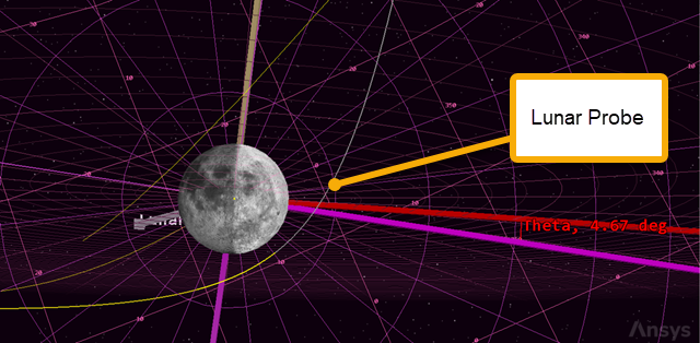
![]()
Trans Lunar Injection First Guess
The trans-lunar injection is not that close. Use a control parameter.
Setting up control parameters to calculate launch and coast times
You need to target the Moon. To achieve that, you will use the launch epoch and the coast time as control parameters. Astrogator will calculate new values that meet a set of constraints. You will use Delta Right Asc and Delta Declination as constraints. The constraints are the targeted differences in the right ascension and declination angles between the spacecraft and the selected central body with respect to its parent body.
- Return to LunarProbe's () Properties ().
- Select Launch () in the MCS.
- Click the Epoch target (
 ).
). - Select Coast () in the MCS.
- Click the Trip target ().
Selecting ToPeriselene's results
Use the multi-component select window to select and define your result.
- Select ToPeriselene () in the MCS.
- Click .
- Expand (
 ) MultiBody (
 ) in the Available Components list in the User-Selected Results - ToPeriselene dialog box.
 - Select Delta Right Asc ().
- Move (
 ) Delta Right Asc () to the selected component list.
 - Select Delta Declination ().
- Move () Delta Declination () to the selected component list.
- Verify that the Moon is the CentralBody for both components in the Component Details list.
- Click to accept your selections and to close the User-Selected Results - ToPeriselene dialog box.
Setting First Guess' Differential Corrector
The Differential Corrector profile uses a differential correction algorithm to achieve a goal value or set of values. The values that the profile targets are called independent variables. The values that define the goal of the profile are called dependent variables. When the target sequence runs, it will change the values of the independent variables to achieve the goal.
- Select First Guess (
 ) in the MCS.
 - Click Differential Corrector in the Name field of the Profiles panel.
- Rename Differential Corrector to Delta RA.
- Click Properties... () in the Profiles toolbar.
You can also double-click on the Differential Corrector to open its properties.
Selecting Delta RA's Control Parameters
Any element of a nested MCS segment or linked component that you can use as an independent variable is marked by a target icon (![]() ), which you selected earlier.
), which you selected earlier.
- Select the Use check box for Launch.Epoch in the Control Parameters panel of the Delta RA dialog box.
- Enter 1 min in the Perturbation field.
- Enter 1 hr in the Max. Step field.
- Select the Use check box for StoppingConditions.Duration.TripValue.
- Enter 5 min in the Max. Step field.
Selecting Delta RA's Equality Constraints (Results)
These are results you selected earlier.
- Select the Use check box for Delta-Declination in the Equality Constraints (Results) panel.
- Select the Use check box for Delta_Right_Asc.
- Keep Desired Value at 0 deg for both.
Setting Delta RA's convergence criteria
Use the Convergence tab to specify convergence criteria and related parameters for the profile. You will set the maximum number of iterations your desire in your analysis. This property defines the maximum number of evaluations that the profile will execute. If the profile does not reach the Desired Value, it will stop after the last iteration. The iteration count includes steps taken while searching for bounds as well as bisection iterations.
- Select the Convergence tab.
- Enter 100 in the Maximum Iterations field.
- Click to accept your changes and to close the Delta RA dialog box.
- Click .
Rerunning the First Guess Target Sequence
By default, the Action field of the Target Sequence is set to Run nominal sequence. If you run the MCS, the values you have set for the various segments (e.g. 90 min Duration for the Coast segment) will be used. Here, instead, you will let the Target Sequence calculate new values to help achieve your goal of reaching the Moon.
- Select First Guess () in the MCS.
- Open the Action drop-down list.
- Select Run active profiles.
- Click Run Entire Mission Control Sequence () in the MCS toolbar.
The Target Sequence will run through several iterations and, after a short time, will converge on a solution that meets your constraints within the specified tolerances. The Target Sequence dialog box will indicate the number of iterations that were required and, again, the differences (now small enough to be acceptable) between the achieved and desired values for the constraints. It will also show the new values calculated for the control variables (launch epoch and coast time).
Viewing the iterations in the Moon-Centered window
Review the results of the solution in the Moon-Centered 3D Graphics window.
- Bring the Moon-Centered window to the front.
- Right-click on Moon () in the Object Browser.
- Select Zoom To in the shortcut menu.
- Select Moon-Centered in the second shortcut menu.
- Use your mouse so that you can see the iterations and the final solution of LunarProbe () reaching the Moon.
![]()
Trans lunar injection: moon targeted
Understanding B-plane targeting
The
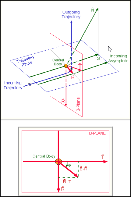
B-plane targeting
Creating a B-plane template with the B-Plane Template tool
The SatPro capability extends the STK software into the realm of high fidelity satellite systems modeling and analysis. SatPro provides you with a collection of satellite engineering tools, including the
Create a new B-plane template with the Moon as the Central Body.
- Select LunarProbe () in the object browser.
- Open the Satellite menu at the top of the STK application.
- Select B-Plane Template... in the shortcut menu.
- Click in the B-Plane Template dialog box.
- Open the Central Body drop-down list.
- Select Moon.
- Click to accept your selection and to close the B-Plane Template dialog box.
Visualizing the B-plane
You can add the B-plane for visualization, enabling you to see what the target sequence is trying to achieve.
- Return to LunarProbe's () Properties ().
- Select the 3D Graphics - B-Plane page.
- Click .
Selecting the event epoch
Enter the epoch of the event. You'll use the Stop time of the First_Guess_ToPeriselne time instant.
- Open the Event Epoch drop-down list.
- Select Time Component in the drop-down list.
- Select LunarProbe () in the object list when the Select Time Instance dialog box.
- Expand () MCSEphemerisSegments (
 ) in the Time Instants for: LunarProbe list.
 - Expand () First_Guess_ToPeriselne (
 ).
). - Select Stop (
 ).
). - Click to accept your selection and to close the Select Time Instance dialog box.
- Click to close the Add B-Plane dialog box.
Updating the display of the target points
The position of the target points can be defined manually.
- Enter 0 km in the B*T field in the Target Point panel.
- Enter 5000 km in the B*R field.
Clearing the graphics
Clear the iteration graphics from the run.
- Select the Basic - Orbit page.
- Click Clear Graphics (
 ) in the MCS toolbar.
 - Click to accept your changes and to keep the Properties Browser open.
Setting up the Moon-Centered view
View the changes in the Moon-Centered 3D Graphics window.
- Bring the Moon-Centered window to the front.
- Use your mouse to set up your view so that it looks similar to the following image:
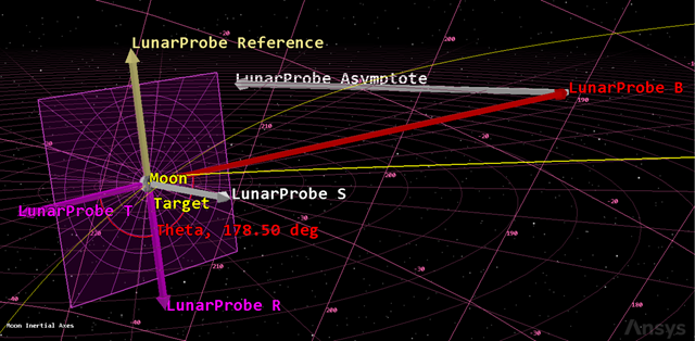
B-plane reference with vectors
Targeting the B-plane
Assume that you want to capture the Moon in an orbit with a 90-degree inclination.
- Return to LunarProbe's () Properties ().
- Select First Guess () in the MCS.
- Select Delta RA in the Profiles panel.
- Click Duplicate (
 ) in the Profiles toolbar.
 - Rename the new profile to B-Plane Targeting.
Selecting the results of the Propgate segment
Select BdotR and BDotT as the results of the ToPeriselene Propagate segment.
- Select ToPeriselene () in the MCS.
- Click .
- Expand () MultiBody () in the Available Components list in the User-Selected Results - ToPerisele dialog box.
- Move () BDotR () to the selected components list.
- Move () BDotT () to the selected components list.
- Click to accept your selections and to close the User-Selected Results - ToPerisele dialog box.
Setting up the B-Plane targeting profile
Select the control parameters and equality constraints of the B-Plane Target Sequence.
- Select First Guess () in the MCS.
- Select B-Plane Targeting in the Profiles panel.
- Click Properties... () in the Profiles toolbar.
- Verify that the two Control Parameters remain selected in the B-Plane Targeting dialog box.
- Clear the Use check boxes for the following in the Equality Constraints (Results) list:
- Delta_Declination
- Delta_Right_Asc
- Select the Use check boxes for the following in the Equality Constraints (Results) list:
- BDotR
- BDotT
- Select BDotR.
- Enter 5000 km in the Desired Value field.
- Click to accept your selection and to close the B-Plane Targeting dialog box.
BDotT is targeted to 0 km and BDotR is targeted to a non-zero value to generate a polar orbit. BDotR is targeted to 5,000 km to avoid having the orbit intersect the Moon, which has a radius of approximately 1,738 km.
Running the Target Sequence to achieve B-plane parameters
With your parameters updated, run the First Guess Target Sequence.
- Select First Guess () in the MCS.
- Click Run Entire Mission Control Sequence () in the MCS toolbar.
- In the Target Sequence dialog box, note that targeting has converged and that new values have been calculated for the control variables
It is important to remember that the B vector ends at the point where the asymptote pierces the plane, not where the trajectory does. Think of the asymptote as the trajectory that the spacecraft would follow if the central body had no gravity. As a result, the trajectory is always closer to the central body than the B vector
Approaching the Moon
You have reached periselene, but unless you perform some kind of maneuver, the spacecraft will swing by the Moon. Before you add the lunar orbital insertion sequence, observe the effects of the Moon's gravity field by inserting a new Propagate segment.
- Bring LunarProbe's () Properties () to the front.
- Right-click on the last (bottom) Return segment () in the MCS.
- Select Insert Before... in the shortcut menu.
- Select Propagate () in the Segment Selection dialog box.
- Click to accept your selection and to close the Segment Selection dialog box.
Updating the Propagate segment's properties
Rename the Propagate segment and change its color.
- Select Propagate () in the MCS.
- Click Segment Properties () in the MCS toolbar.
- Enter Prop3Days in the Name field in the Edit Segment dialog box.
- Open the Color drop-down list.
- Select a color that contrasts with those of the other Propagate segments.
- Click to accept your selections and to close the Edit Segment dialog box.
Changing Prop3Days' parameters
Update the Prop3Days Propagate segment's propagator and trip time.
- Select Prop3Days () in the MCS.
- Click the Propagator ellipsis ().
- Select Moon HPOP Default v10 () in the Select Component dialog box.
- Click to accept your selection and to close the Select Component dialog box.
- Enter 3 day in the Trip field.
- Click .
- Click Run Entire Mission Control Sequence () in the MCS toolbar.
Clearing the graphics
Clear the iteration graphics from the run.
- Bring LunarProbe's () Properties () to the front.
- Click Clear Graphics () in the MCS toolbar.
- Click .
Visualizing the LunarProbe swinging by the Moon
View the results of the run in the Moon-Centered 3D Graphics window.
- Bring the Moon-Centered window to the front.
- Set your view so that you can see LunarProbe () swing by the Moon.
LunarProbe swings past the Moon
Creating a new Target Sequence to achieve LOI
Without any targeting parameters, LunarProbe will swing by the Moon. Use a Target Sequence to conduct a burn and enter an orbit around the Moon.
Inserting a new Target Sequence
Create a new Target Sequence and nest the Prop3Days Propagate segment in it.
- Return to LunarProbe's () Properties ().
- Right-click on Prop3Days () in the MCS.
- Select Insert Before... in the shortcut menu.
- Select Target Sequence () in the Segment Select dialog box.
- Click to accept your selection and to close the Segment Select dialog box.
- Drag Prop3Days () to nest it in Target Sequence ().
- Right-click on Target Sequence () in the MCS.
- Select Rename in the shortcut menu.
- Rename Target Sequence () to Lunar Orbit Insertion.
Inserting a Maneuver segment
Insert a maneuver segment before the Prop3Days Propagate segment in the Lunar Orbit Insertion Target Sequence.
- Right-click on Prop3Days () in the MCS.
- Select Insert Before... in the shortcut menu.
- Select Maneuver () in the Segment Selection dialog box.
- Click to accept your selection and to close the Segment Select dialog box.
Updating the Maneuver segment properties
You will now perform an impulsive maneuver to capture the Moon in a circular orbit.
- Right-click Maneuver () in the MCS.
- Select Properties... in the shortcut menu.
- Enter LOI in the Name field of the Edit Segment dialog box.
- Open the Color drop-down list.
- Select white.
- Click to accept your changes and to close the Edit Segment dialog box.
Updating LOI's parameters
You will need to do a burn in a direction opposite to Moon-centered velocity to slow down and capture into a lunar orbit.
- Select LOI () in the MCS.
- Select the Attitude tab.
- Open the Attitude Control drop-down list.
- Select Thrust Vector in the shortcut menu.
- Click the Thrust Axes ellipsis ().
- Select Satellite in the object list in the Select Reference dialog box.
- Select VNC(Moon) (
 ) in the Templates for Satellite list.
 - Click to accept your selection and to close the Select Reference dialog box.
- Select the X(Velocity) target () to set the control variable.
- Click .
Setting LOI's results
Set the Results of the LOI Maneuver segment to achieve an eccentric orbit around the Moon.
- Select LOI () in the MCS.
- Click .
- Expand () Keplerian Elements () in the User-Selected Results - LOI dialog box.
- Move () Eccentricity () to the selected components list.
- Double-click CentralBody in the Component Details list.
- Select Moon () in the Component Selection dialog box.
- Click to accept your selection and to close the Component Selection dialog box.
- Click to close the User-Selected Results - LOI dialog box.
Setting up Lunar Orbit Insertion's Differential Corrector
Select the control parameters and equality constraints of the Lunar Orbit Insertion Target Sequence.
- Select Lunar Orbit Insertion () in the MCS.
- Select Differential Corrector in the Profiles panel.
- Click Properties... () in the Profiles toolbar.
- Select Use - ImpulsiveMnvr.Pointing.Cartesian.X in the Control Parameters panel in the Differential Corrector dialog box.
- Select Use - Eccentricity in the Equality Constraints (Results) panel.
- Leave the Desired Value for Eccentricity at 0, since you want to circularize the orbit.
- Click to accept your changes and to close the Differential Corrector dialog box.
Running the entire mission control sequence
Run the entire MCS with the Lunar Orbit Insertion Target Sequence.
- Open the Action drop-down list.
- Select Run active profiles.
- Click Run Entire Mission Control Sequence () in the MCS toolbar.
- Bring LunarProbe's () Properties () to the front.
- Click Clear Graphics () in the MCS toolbar.
- Click .
When the targeter converges, the Target Sequence dialog box will indicate that a near-zero value for eccentricity has been achieved.
Visualizing LunarProbe entering a Moon orbit
View the LOI in the Moon-Centered 3D Graphics window.
- Bring the Moon-Centered 3D Graphics window to the front.
- Set your view so that you can see LunarProbe () entering a circular orbit around the Moon.
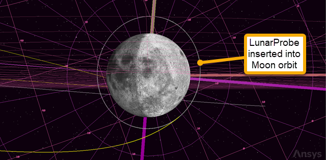
LunarProbe orbiting the moon
Creating a summary report
You can also confirm the value of eccentricity and other targeted orbital elements by running a Summary report.
- Bring LunarProbe's () Properties () back to the front.
- Select LOI () in the MCS.
- Click Segment Properties () in the MCS toolbar.
- Click the Coord. System ellipsis () in the Edit Segment dialog box.
- Select Moon () in the object list in the Select Reference dialog box.
- Select Inertial (
 ) in the Systems for: Moon list.
 - Click to accept your selection and to close the Select Reference dialog box.
- Click to close the Edit Segment dialog box.
- Click .
- Click Summary (
 ) in the MCS toolbar to view the report.
Among other things, you will find that the targeted values for eccentricity (0) were achieved within tolerance.
Saving your work
- Close any open reports, properties and tools.
- Save () your work.
Summary
In this exercise, you explored a mission to the Moon using the B-plane targeting method. After setting up the scenario, running the MCS, and using a trans-lunar injection first guess, you ran the B-plane targeting tool and set up the targeter to approach the Moon. This calculated the launch epoch and coast duration. Finally, after completing a lunar orbit insertion, the satellite finally entered a circular orbit around the Moon.