Polyline Primitive

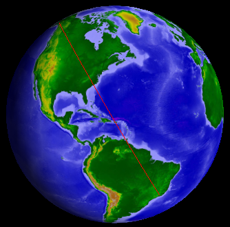
Polylines render lines on the ground or in space. Polylines are used to visualize many things including satellite orbits, country borders, and range rings. Polylines accept interpolators that allow them to render great arc or rhumb lines. Every line segment in a polyline can have the same color or each can have a different color. The polyline can be translucent and has a width, defined in pixels.

The following example from the GraphicsHowTo shows how to create a polyline with two points:

[C#] Copy Code
IAgStkGraphicsSceneManager manager = ((IAgScenario)root.CurrentScenario).SceneManager;
Array philadelphia = new object[]
{
     39.88, -75.25, 3000.0
};
Array washingtonDC = new object[]
{
     38.85, -77.04, 3000.0
};

Array positions = new object[6];
philadelphia.CopyTo(positions, 0);
washingtonDC.CopyTo(positions, 3);

IAgStkGraphicsPolylinePrimitive line = manager.Initializers.PolylinePrimitive.Initialize();
line.SetCartographic("Earth", ref positions);
manager.Primitives.Add((IAgStkGraphicsPrimitive)line);

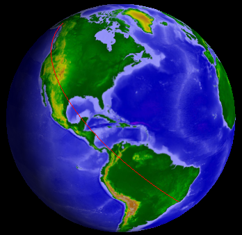
An equally useful use-case is rendering several line segments with one polyline primitive. Line segments can be connected, as they would be for a country border, or independent, as they would be for individual aircraft routes. The Set and SetCartographic methods can also be used to define a polyline with several line segments. They take a collection of positions that define the polyline.

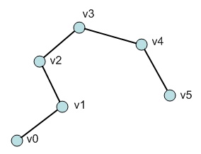
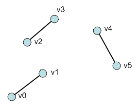
The type of line can be specified when constructing a polyline. When LineStrip is used, the positions define a connected line strip. After the first position, each additional position connects to the previous. When Lines is used, every two positions define an individual line segment. The difference is shown in the image below.

LineStrip

Lines

The following example initializes a polyline with 3 line segments.

[C#] Copy Code
IAgStkGraphicsSceneManager manager = ((IAgScenario)root.CurrentScenario).SceneManager;
Array positions = new object[]
{
     1, 0, 0,
     3, 0, 0,
     0, 1, 0,
     0, 3, 0,
     0, 0, 0,
     3, 3, 0
};

IAgStkGraphicsPolylinePrimitive line = manager.Initializers.PolylinePrimitive.InitializeWithType(
AgEStkGraphicsPolylineType.eStkGraphicsPolylineTypeLines);
line.SetCartographic("Earth", ref positions);
manager.Primitives.Add((IAgStkGraphicsPrimitive)line);

Polylines support the standard color properties: Color and Translucency, which affect every line segment. Polylines can also be rendered with an outline by using DisplayOutline, OutlineColor, OutlineTranslucency, and OutlineWidth:

Width: 2
Color: Yellow
DisplayOutline: false (default)

Width: 2
Color: Yellow
DisplayOutline: true
OutlineWidth: 2
OutlineColor: Black

To define a polyline with per-line segment colors, use a Set or SetCartographic method that takes a separate collections of colors, one color per position.

Each color in the collection corresponds to a position in the positions collection, so the number of colors must match the number of positions. Currently, flat shading is used; of the two positions that define a line segment, the color of the second one is used for the color of the line segment.

The following example uses a polyline to render 3 lines, each with a different color.

[C#] Copy Code
IAgStkGraphicsSceneManager manager = ((IAgScenario)root.CurrentScenario).SceneManager;

Array positions = new object[]
{
     1000000, 0, 0,
     7000000, 0, 0,
     0, 1000000, 0,
     0, 7000000, 0,
     0, 0, 1000000,
     0, 0, 7000000
};

Array colors = new object[]
{
     (uint)Color.Blue.ToArgb(),
     (uint)Color.Blue.ToArgb(),
     (uint)Color.Orange.ToArgb(),
     (uint)Color.Orange.ToArgb(),
     (uint)Color.White.ToArgb(),
     (uint)Color.White.ToArgb()
};

IAgStkGraphicsPolylinePrimitive line = manager.Initializers.PolylinePrimitive.InitializeWithType(AgEStkGraphicsPolylineType.eStkGraphicsPolylineTypeLines);
line.SetWithColors(ref positions, ref colors);
((IAgStkGraphicsPrimitive)line).ReferenceFrame = root.VgtRoot.WellKnownSystems.Earth.Inertial;

manager.Primitives.Add((IAgStkGraphicsPrimitive)line);

To facilitate dynamic updates, polylines provide SetPartial and SetPartialCartographic methods. See the Dynamic Updates Overview.

Interpolators

A theme throughout primitives is to decouple computation from rendering. For the polyline, this means that an interpolator can be provided as input along with positions to the polyline. The interpolator computes the actual positions rendered. When a polyline is dynamically changed via a Set method, the interpolator is automatically called. This makes the polyline useful for rendering a wide range of line-based objects: lines, great arcs, rhumb lines, splines, etc.

Great Arcs

Great arcs are paths on the surface that represent the shortest distance between positions. They are rendered by passing a great arc interpolator to a polyline as shown below.

[C#] Copy Code
IAgStkGraphicsSceneManager manager = ((IAgScenario)root.CurrentScenario).SceneManager;
Array positions = new object[]
{
     61.22, -149.85, 0,
     -22.54, -43.14, 0
};

IAgStkGraphicsPositionInterpolator interpolator = manager.Initializers.GreatArcInterpolator.Initialize() as IAgStkGraphicsPositionInterpolator;
IAgStkGraphicsPolylinePrimitive line = manager.Initializers.PolylinePrimitive.InitializeWithInterpolator(interpolator);
line.SetCartographic("Earth", ref positions);

manager.Primitives.Add((IAgStkGraphicsPrimitive)line);

This results in the following image:

Rhumb Lines

Rhumb lines are lines of constant bearing. They appear as straight lines on a Mercator 2D map projection and are well suited to navigation. Replace GreatArcInterpolator in the above code example with RhumbLineInterpolator to render a rhumb line. The result is shown below:

To maintain a constant bearing, the rhumb line appears to spiral, unlike the great arc which is the shortest distance between the points.

No Interpolation

When a polyline is constructed with no interpolator, no interpolator is used. This is always faster than using an interpolator since no interpolated positions need to be computed and no extra memory will be allocated. It is common to not use an interpolator when the vertices are not on the surface or are already close enough together that the line doesn't appear to cut through the globe.

Interpolator Granularity

Both the great arc and rhumb line interpolators provide a Granularity property that is used to control the number of interpolated positions. The default is 1 degree. Decrease the granularity to add more positions or increase it to add fewer positions. Beware, however, that making the granularity too high will result in lines cutting through the globe, as the following example demonstrates.

[C#] Copy Code
IAgStkGraphicsSceneManager manager = ((IAgScenario)root.CurrentScenario).SceneManager;
Array positions = new object[]
{
     61.22, -149.85, 0,
     -22.54, -43.14, 0
};

IAgStkGraphicsPolylinePrimitive line = manager.Initializers.PolylinePrimitive.InitializeWithInterpolator(
manager.Initializers.RhumbLineInterpolator.InitializeWithCentralBodyAndGranularity(
"Earth", 30) as IAgStkGraphicsPositionInterpolator);
line.SetCartographic("Earth", ref positions);

manager.Primitives.Add((IAgStkGraphicsPrimitive)line);

STK Programming Interface 11.0.1