This tutorial demonstrates how to build six different application types using five different programming languages while covering all major parts of the Ansys Systems Tool Kit® (STK®) Object Model (STK OM).
It is designed to be used as:
-
Course material for instructor-led training
-
A self-paced tutorial for independent study
Goal of the tutorial
The main goal of the tutorial is to provide you with the necessary background information for using the STK Object Model. The tutorial is not intended to replace existing tutorials and code samples. On the contrary, it is meant to provide the proper prospective and to help you understand the existing materials.
Code snippets and example applications in the programming help are geared toward .net languages, C#, and vb.net. Throughout this tutorial, differences and similarities will be pointed out between the programming languages.
This tutorial barely scratches the surface of the STK Object Model. Even after actively using the STK Object Model, you will need to use the reference documentation as an additional resource. Instead of following the approach of most other tutorials that focus on the “how,” this tutorial aims to explain the "why." Each section of the code is designed to be a mini lesson. Important concepts may be repeated or explained in several places.
Sample code in the tutorial
To make the sample code more readable in the tutorial, the instructions for creating the container applications are separated from the actual STK OM code. Furthermore, all of the STK OM code is included within the same “RunCode” method, so that it can easily be separated from the instructions for the container applications. The sample code is designed to cover all main parts of the STK OM and not represent a “real life” problem.
Development of the STK Object Model
STK OM follows the logic of the STK desktop application. When AGI developers created the STK OM project, they named it STK Engine. Their idea was that future versions of the STK desktop application would be created on top of the STK Engine. That idea was never fully realized, but the result was that the object model closely follows the workflow of the user interface.
History of the customization of the STK application using the Object Model
The following provides the history of the customization of the STK application. Each time AGI introduced new features and capabilities, AGI developers had to decide if they wanted the new interfaces to follow the workflow of the old code or apply what they learned from using the Object Model. In most cases, they chose to remain consistent with the exception of the brand new modules in the STK application, such as the STK/Astrogator® capability, Analysis Workbench, and Aviator.
Originally, the only way to programmatically modify the STK application was through Connect Commands. The outside applications were able to establish a TCP/IP connection with the STK application and exchange string commands. While the STK Object Model was created as a replacement for Connect commands, you can still use Connect commands as part of the STK OM. The Connect commands are still important, as they fill in certain gaps in the STK Object Model.
STK application version 5 was the first Windows Operating System-only version of the application. One of the new features was the HTML browser control. The purpose of the control was to enable users to create custom user interfaces and communicate with the STK application through Connect commands. Some of the first work on the STK Object Model was done at this time. The pattern of getting the application object and the STK application root object was established at this time.
STK application version 7 introduced the STK Object Model. The only application types available at the time were stand-alone applications. At the same time, the STK Object Model automated only a portion of the functionality available in the STK Desktop application, focusing on the primary objects in the STK application . This required a high reliance on Connect commands to fill in the gaps.
STK application version 8 expanded the code coverage to analysis objects and group objects (chains and constellations).
STK application version 9 presented a major expansion of the STK Object Model. It added the ability to control the STK application from outside applications as well as from inside the STK application in four of the UI Plugins. STK 9 also included the Astrogator propagator and Vector Geometry Tool (VGT).
STK application version 10 saw the creation of Analysis Workbench. Analysis Workbench consisted of two new modules, the Time Tool and the Calculation Tool, in addition to the existing Vector Geometry Tool (VGT). Since the STK application already had the VGT interface as part of the IAgStkObject, developers had three choices: replace the VGT interface with the new Analysis Workbench interface, add the Time Tool and Calculation Tool as independent interfaces to the IAgStkObject, or add all Analysis Workbench functionality to the VGT interface. We choose the third option, as attempting to maintain backward compatibility overrode the need to present logical property names.
STK application version 10 featured a brand new visualization. The visualization code was originally developed for the Components product and integrated into this version. Before STK application version 10, the only way to interact with 2D and 3D windows was through Connect commands. The new visualization code included a very powerful graphic primitives library. The library enables developers to draw objects on the globe space and screen space as well as manipulate the camera object. However, due its complexity, it is not possible to save graphics primitives with the scenario.
STK application version 11 added support for child objects, such as transmitters, radars, etc., and the Beta version of the Aviator object model.
Using the STK Desktop application as a guideline when creating Object Model code
Since the Object Model closely follows the workflow of the user interface (UI), you can use the UI up to a point as a guideline when writing code. For example, if you change the label for a facility, notice that the IAgFacility interface contains the Graphics property, which in turn contains the LabelName property. According to the STK Programming Interface help, the LabelName property is a string type and a read-write property, so, the following line will work:
facility.Graphics.LabelName = "Facility Name";
Your code will compile, but when you actually run the code, you will get the error, “LabelName is read only property.” If you take a look at the STK Desktop application, the equivalent user interface looks like this:
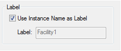
As you can see, to change the label, you have to uncheck the “Use Instance Name as Label” checkbox. Since the object model follows the same logic as the user interface, the correct code is:
facility.Graphics.UseInstNameLabel = false;
facility.Graphics.LabelName = "Facility Name";
Another example is vehicle propagators. If you take a look at satellite properties in the STK Desktop application, the Orbit section allows users to select among thirteen propagators. Some propagators are very similar to each other, while others are completely different. However, they perform the same function, which is defining the satellite's orbit. The STK application is designed to accept new propagators as long as they follow the same interface pattern. As long as a propagator implements the correct interface, the STK application will accept the propagator as a valid option. This concept is more obvious when working with external plugins. This paradigm will be discussed more when explaining the Factory and Casing concepts.
Important concepts
Units
The STK application is a very versatile application. It accepts and reports data using many unit types. As a result, the Object Model has to be able to pass through values of various data types. For example, the Facility object contains the Position object. The first time you would expect to see “Latitude” and “Longitude” properties of a numeric type are as part of the Position object. But, if you take a look at the documentation, the Position object implements the IAgPosition interface. The interface does not contain Latitude and Longitude properties, but several assign and query methods. Here is the code to get the latitude and longitude:
object latitude = 0, longitude = 0; double altitude = 0;
facility.Position.QueryPlanetodetic(out latitude, out longitude, out altitude);
You will notice that latitude and longitude are of the object type, while altitude is a numeric type. Again, you cannot assume that latitude and longitude are numeric because the STK application accepts units such as DMS (degrees, minutes, seconds) as a valid angle unit. In that case, the default latitude (angle) value would be 40:02:18.9960. So, in your code, you need to make sure that you know the units before you get/set values. Imagine that the return value comes in a box of the type object. You can “unbox” the value to a proper numeric type.
Reference parameters
The STK Object Model passes objects by reference, which means that if you assign an object to a variable, the variable contains a pointer to the original object. Modifying the variable will also affect the original object. We will come back to this concept repeatedly. The reason why we are discussing the concept now is the previous example, which is repeated below:
facility.Position.QueryPlanetodetic(out latitude, out longitude, out altitude);
The code above is written in C#. The C# keyword “out” marks latitude, longitude, and altitude variables as reference parameters. The method call will modify the variable. The reference parameters are not available in scripting languages. If you take a look again at the IAgPosition interface documentation, you will see that each “query” method has two versions: one that uses reference parameters and one that returns values in a one dimensional array.
Casting
Another important concept is casting (changing object type). STK Object Model follows C/C++ inheritance logic. This concept might be foreign to .net/Java developers. AgFacility class inherits from both the IAgStkObject and IAgFacility interfaces. However, to pass the object of type AgFacility to a method that accepts IAgStkObject, you have to cast the object back to IAgStkObject; otherwise, you will get a compile error. Some scripting languages, such as JavaScript and MATLAB, do not require casting.
In general, the common methods and properties are located in the parent interface. For example, IAgStkObject is the parent interface for STK objects, IAgGraphicsPrimitive for graphics primitives, and IAgCrdn for Analysis Workbench.
Factory
Factory is an object-oriented programming concept. It describes an object for creating new objects. The factory object was hidden in previous versions of the STK application, but with the introduction of Graphics Primitives and the Vector Geometry (Analysis Workbench), the factory method of creating a new object was made public.
For example, the vector factory is used to create any new vector. The factory creates an object of the type Aggravator. To use the new vector, you need to cast the vector to the appropriate subtype. The principle is the same as the "New" method of the IAgStkObject's Children property.
The factory concept is used to support extensibility of the STK Desktop application. It enables you to create new objects and interfaces without interfering with existing objects. As the STK Object Model closely follows the desktop application, the STK Object Model works on the same principle. And this principle is the main reason why the STK Object Model has so much casting.
Categories of custom applications
A custom STK application falls into one of these three categories, depending on how it interacts with the STK desktop application:
Extend STK. Runs as part of the STK desktop application.
Automate STK. Controls the STK desktop application.
Develop a custom application. Runs independently from the STK desktop application.
Extend the STK application
To extend the STK GUI and the STK analysis engine, you can use:
-
HTM pages inside the STK application
-
A UI plugin
HTML pages hosted through the Web Browser control is the original method for creating custom user interfaces inside the STK application. Later, AGI added pluggable points that enable users to extend calculations and the user interface. The calculation plugins use a subset of the STK Object Model. The restriction was necessary, to prevent circular references.
Automate the STK application
To automate repetitive tasks, you can:
-
Connect to an instance of the STK application.
-
Create an instance of the STK application.
The applications that control the STK Desktop application can either connect to an existing instance of the STK Desktop application or create a new instance of it. Often, the Automation application first tries to connect to an existing instance of the STK Desktop application, and if there is no open instance, it creates a new one. The Automation application is perfect for acting as a bridge between the STK Desktop application and external data sources.
Develop a custom application
To develop a custom software application that embeds the STK analysis and visualization engine, you can use:
-
A stand-alone application with ActiveX controls
-
A stand-alone application without ActiveX controls
Choose the right programming language
The following table shows the programming languages for the variety of ways that you can extend, automate, and build custom applications.
|
Task |
JavaScript |
C# |
VB.net |
Java |
MATLAB |
Python |
|---|---|---|---|---|---|---|
|
HTML Inside the STK application |
Yes |
|||||
|
UI Plugin |
Yes |
Yes |
||||
|
Create new instance of the STK application |
Yes |
Yes |
Yes |
Yes |
Yes |
|
|
Connect to existing instance of the STK application |
Yes |
Yes |
Yes |
Yes |
Yes |
|
|
Stand-alone application with ActiveX controls |
Yes |
Yes |
Yes |
Yes |
Yes |
|
|
Stand-alone application without ActiveX controls |
Yes |
Yes |
Yes |
Yes |
Yes |
It is possible to create a stand-alone HTML page with an imbedded ActiveX control, but that approach is no longer recommended due to browser settings and security reasons.
Scenario
Now that you have the STK Root object, you need to create an STK scenario. The STK Root object has methods to create a new scenario or load an existing scenario.
|
[C#] |
| //Create new scenario
root.NewScenario("Test"); |
|
[Java] |
| //Create new scenario
root.newScenario("Test"); |
|
[MATLAB] |
| %Create new scenario
root.NewScenario('Test'); |
|
[Python] |
| #Create new scenario
root.NewScenario('MyFacility') |
There can be only one scenario open at a time.
The usual workflow of the STK Object Model applications is to set up the STK objects, establish a relationship between objects, perform analysis, and get results of the analysis.
Connect commands still have a role in the STK Object Model. One of the areas that is not covered by the STK Object model is 3D Globe properties. If you want to hide reference frame information on the 3D Globe window, the only way is to use a Connect command:
|
[C#] |
| //Execute connect command
root.ExecuteCommand("VO * Annotation Frame Show Off"); |
|
[Java] |
| //Execute connect command
root.executeCommand("VO * Annotation Frame Show Off"); |
|
[MATLAB] |
| %Execute connect command
root.ExecuteCommand('VO * Annotation Frame Show Off'); |
|
[Python] |
| #Execute connect command
root.ExecuteCommand('VO * Annotation Frame Show Off') |
If the Connect command fails, the ExecuteCommand method will raise an exception. A preferred method is to create a wrapper for the ExecuteCommand in a separate method and handle any possible exceptions in that method.
The next step is to set up STK objects. The STK application has five main groups of objects: static/fixed objects (facility, place, and target), moving/vehicles (airplane, satellite, etc.), analysis objects (access and coverage), object groups (chain and constellation), and subobjects (antenna, receiver, transmitter, etc.).
Create a static STK object (facility). All the new objects are attached to an existing parent object. Usually, the new objects are added to the Children collection of the scenario.
|
[C#] |
| //Create Static STK Object (facility)
AgFacility facility = root.CurrentScenario.Children.New(AgESTKObjectType.eFacility, "MyFacility") as AgFacility; |
|
[Java] |
| //Create Static STK Object (facility)
AgFacilityClass facility = (AgFacilityClass)root.getCurrentScenario().getChildren()._new(AgESTKObjectType.E_FACILITY, "MyFacility"); |
|
[MATLAB] |
| %Create Static STK Object (facility)
facility = scenario.Children.New('eFacility','MyFacility'); |
|
[Python] |
| #Create Static STK Object (facility)
facility = scenario.Children.New(STKObjects.eFacility, 'MyFacility') facility2 = facility.QueryInterface(STKObjects.IAgFacility) |
The “New” method returns an object of the “IAgStkObject” type. You have three choices: keep the object as IAgStkObject, cast the object to IAgFacility, or cast the object to the AgFacility, which contains both IAgStkObject and IAgFacility interfaces. On the surface, AgFacility looks like obvious choice, but most of the code samples use the IAgFacility interface. Originally, there were issues using Ag*** classes. As a result, the original recommended usage of the IAg*** interfaces. AGI has resolved issues with the underlying code and are in the process of updating code samples and documentation. All methods return IAg*** objects.
Change the position of the facility to latitude 40 and longitude -80. By default, new facility and place objects are created at AGI’s main office location. Also, the default for position units are degrees. So, the following code will work in a new application:
|
[C#] |
| facility.Position.AssignPlanetodetic(40, -80, 0); |
|
[Java] |
| facility.getPosition().assignPlanetodetic(40,-80, 0); |
|
[MATLAB] |
| facility.Position.AssignPlanetodetic(40,-80, 0) |
|
[Python] |
| facility2.Position.AssignPlanetodetic(40,-80,0) |
Don't make the mistake of assuming that you can use angle units as degree units. Be safe and set the unit to degrees before setting the position. Position units are special units and different for latitude and longitude. The longitude values can be in either -180 to 180 range or 0 to 360 range. As result, longitude units are unique and different from latitude units. The correct code is:
|
[C#] |
| root.UnitPreferences.SetCurrentUnit("LatitudeUnit", "deg");
root.UnitPreferences.SetCurrentUnit("LongitudeUnit", "deg"); facility.Position.AssignPlanetodetic(40, -80, 0); |
|
[Java] |
| root.getUnitPreferences().setCurrentUnit("LatitudeUnit", "deg");
root.getUnitPreferences().setCurrentUnit("LongitudeUnit", "deg"); facility.getPosition().assignPlanetodetic(40,-80, 0); |
|
[MATLAB] |
| root.UnitPreferences.Item('LatitudeUnit').SetCurrentUnit('deg')
root.UnitPreferences.Item('LongitudeUnit').SetCurrentUnit('deg') facility.Position.AssignPlanetodetic(40,-80, 0) |
|
[Python] |
| root.UnitPreferences.Item('LatitudeUnit').SetCurrentUnit('deg'))
root.UnitPreferences.Item('LongitudeUnit').SetCurrentUnit('deg') facility2.Position.AssignPlanetodetic(40,-80,0) |
Take a look at the code used to get the current position of the facility. The C# version of the code uses "out" parameters, which means that variables are passed by reference and modified inside the method. However, it was already mentioned that other languages do not support "out" parameters. The API provides an alternative method for each method that uses "out" parameters. Here are examples of code in Java, C# and MATLAB respectively:
double lat, lon, alt;
AgSafeArray positions = facility.getPosition().queryPlanetodeticArray();
lat = Double.parseDouble(positions.getJavaObject(0).toString());
lon = Double.parseDouble(positions.getJavaObject(1).toString());
alt = Double.parseDouble(positions.getJavaObject(2).toString());
object lat, lon; double alt, latValue, lonValue;
facility.Position.QueryPlanetodetic(out lat, out lon, out alt);
latValue = double.Parse(lat.ToString());
lonValue = double.Parse(lon.ToString());
positions = facility.Position.QueryPlanetodeticArray()
lat = positions(1)
lon = positions(2)
alt = positions(3)
The second difference between languages is how they "unbox" latitude and longitude values. While MATLAB, as do other scripting languages, takes advantage of late binding and performs a conversion for you, the compiled languages require implicit casting. The Java interface requires an additional step of converting an object to a "Java Object". This was done in order to support the Java interface on both Windows and Linux operating systems.
The previous code shows how to set and get a cartodetic (latitude, longitude, altitude) position for a static STK object. If you take a look at the Programming Help, the "Position" property is of the type IAgPosition located in the AGI Utility library (AgUtil). Since you can set a position using cartesian coordinates (x,y,z) and get a (query) position for cartodetic values, you can use the interface to convert a position between different coordinate types. Originally, the only way of accessing the IAgPosition interface was by creating a dummy STK object and using the object for conversion. Now you can access all unit conversations through the conversation utility available on the STK root object.
Check if GUI and OM units are the same.
Modify graphics - change facility's label to “My Facility”
The STK Object Model follows the logic of the STK desktop application. When AGI created the STK Object Model, the original name for the project was STK Engine. The idea was that future versions of the STK desktop application user interface would be created on top of the STK Engine. AGI never realized the idea, but the result was that the object model closely follows the workflow of the user interface. For example, if you change the label for facility, IAgFacility interface contains the Graphics property, which in turn contains the LabelName property. According to the STK Programming help, the LabelName property is a string type and read-write property. So the following line should work:
|
[C#] |
| //Modify graphics - change facility's label
facility.Graphics.LabelName = "My Facility"; |
|
[Java] |
| //Modify graphics - change facility's label
facility.getGraphics().setLabelName("My Facility"); |
|
[MATLAB] |
| %Modify graphics - change facility's label
facility.Graphics.LabelName = 'My Facility'; |
|
[Python] |
| #Modify graphics - change facility's label
facility2.Graphics.LabelName = 'My Facility' |
Your code would compile, but when you actually run the code, you will get an error that the LabelName is a read only property. If you take a look at the STK Desktop application, an equivalent user interface looks like this:
As you can see, to change the label, you have to uncheck the “Use Instance Name as Label” checkbox. Since the object model follows the same logic as the user interface, the correct code is:
|
[C#] |
| //Modify graphics - change facility's label
facility.Graphics.UseInstNameLabel = false; facility.Graphics.LabelName = "My Facility"; |
|
[Java] |
| //Modify graphics - change facility's label
facility.getGraphics().setUseInstNameLabel(false); facility.getGraphics().setLabelName("My Facility"); |
|
[MATLAB] |
| %Modify graphics - change facility's label
facility.Graphics.UseInstNameLabel = false; facility.Graphics.LabelName = 'My Facility'; |
|
[Python] |
| #Modify graphics - change facility's label
facility2.Graphics.UseInstNameLabel = False facility2.Graphics.LabelName = 'My Facility' |
Add a child object (sensor) to a facility:
The Sensor object belongs to a group of subobjects. The Sensor object cannot exist by itself. Instead, it has to be attached to another object, such as a facility or aircraft. Again, in order to create a new object, you need to add the object to the Children collection of the parent object; but in this case, you are going to do it the “right way” and check if the object exists first:
|
[C#] |
| //Add child object (sensor)
IAgSensor sensor = null; if (facility.Children.Contains(AgESTKObjectType.eSensor, "MySensor") { sensor = (IAgSensor)root.GetObjectFromPath("Facility//MyFacility//Sensor//MySensor"); } else { sensor = facility.Children.New(AgESTKObjectType.eSensor, "MySensor") as IAgSensor; } |
|
[Java] |
| //Add child object (sensor)
AgSensorClass sensor = null; if (facility.getChildren().contains(AgESTKObjectType.E_SENSOR, "MySensor"))
|
|
[MATLAB] |
| %Add child object (sensor)
if (facility.Children.Contains('eSensor','MySensor')) sensor = root.GetObjectFromPath('Facility/MyFacility/Sensor/MySensor'); else sensor = facility.Children.New('eSensor', 'MySensor'); end |
|
[Python] |
| # Add child object (sensor)
if(facility.Children.Contains(STKObjects.eSensor,'MySensor')): sensor = root.GetObjectFromPath('Facility/MyFacility/Sensor/MySensor') else: sensor = facility.Children.New(STKObjects.eSensor,'MySensor') |
There is a lot going on in a couple of lines of code. Review it line by line. You can use the Children collection of the Facility object to check if “MySensor” is already part of the list. If the sensor already exists, you could get the sensor object from the Children collection, but in this case,you are using a “shortcut” way of getting the object directly from the root object. To get the Sensor object, you need to pass the full path to the Sensor object, which also includes the sensor’s parent object. Each line requires casting from IAgStkObject to IAgSensor. C# provides two ways to cast objects and both methods are demonstrated below.
Set the sensor’s pattern to complex conic. The default Sensor object is defined as a simple conic sensor. So, the first step is to change the sensor type to complex conic. Normally, you would need to set all the properties individually to configure an object. However, the sensor pattern is one of a few places where AGI added helper methods:
|
[C#] |
| sensor.SetPatternType(AgESnPattern.eSnComplexConic);
sensor.CommonTasks.SetPatternComplexConic(50, 90, 0, 90); |
|
[Java] |
| sensor.setPatternType(AgESnPattern.E_SN_COMPLEX_CONIC);
sensor.getCommonTasks().setPatternComplexConic(50,90,0,90); |
|
[MATLAB] |
| sensor.SetPatternType('eSnComplexConic')
sensor.CommonTasks.SetPatternComplexConic(50,90,0,90) |
|
[Python] |
| sensor2 = sensor.QueryInterface(STKObjects.IAgSensor)
sensor2.SetPatternType(STKObjects.eSnComplexConic) sensor2.CommonTasks.SetPatternComplexConic(50,90,0,90) |
You can add access constraints to the sensor and set the maximum range to 40 Km.
The Intervisibility or access calculation is starting the calculation for most of the STK analysis. Imagine a two-dimensional coordinate system. Regardless of where you put two distinct points, you can always draw a line between the points. To get an accurate analysis, you need to restrict (constrain) the calculation. You do that by adding access constraints that are part of the access calculation to the object.
|
[C#] |
| //Add range constraint to sensor
IAgAccessCnstrMinMax rangeConstraint = sensor.AccessConstraints.AddConstraint(AgEAccessConstraints.eCstrRange) as IAgAccessCnstrMinMax; rangeConstraint.EnableMax = true; rangeConstraint.Max = 40; |
|
[Java] |
| //Add range constraint to sensor
IAgAccessCnstrMinMax rangeConstraint = (IAgAccessCnstrMinMax) sensor.getAccessConstraints().addConstraint(AgEAccessConstraints.E_CSTR_RANGE); rangeConstraint.setEnableMax(true); rangeConstraint.setMax(40); |
|
[MATLAB] |
| %Add range constraint to sensor
rangeConstraint = sensor.AccessConstraints.AddConstraint('eCstrRange'); rangeConstraint.EnableMax = true; rangeConstraint.Max = 40; |
|
[Python] |
| #Add range constraint to sensor
sensor3 = sensor2.AccessConstraints.AddConstraint(STKObjects.eCstrRange) sensor4 = sensor3.QueryInterface(STKObjects.IAgAccessCnstrMinMax) sensor4.EnableMax = True sensor4.Max = 40 |
Objects in the STK Object Model are passed by reference. Normally, you would expect to create an object, set the object properties, and add the object to a collection. The code above looks unfinished. The rangeConstraint object is modified after it was added to the collection of the access constraints. But because the rangeConstraint object points to the object that is part of the AccessConstraints collection, you do not need to update the collection.
Again, you needed to set “EnableMax” flag to true before you can set “Max” value and the code assumes that distance units are set to Km.
Create a vehicle (aircraft) using Great Arc propagator
|
[C#] |
| //Create vehicle (aircraft) using GreatArc propagator
AgAircraft aircraft = root.CurrentScenario.Children.New(AgESTKObjectType.eAircraft, "MyAircraft") as AgAircraft; aircraft.SetRouteType(AgEVePropagatorType.ePropagatorGreatArc); IAgVePropagatorGreatArc greatArcPropagator = aircraft.Route as IAgVePropagatorGreatArc; |
|
[Java] |
| //Create vehicle (aircraft) using GreatArc propagator
AgAircraftClass aircraft = (AgAircraftClass)root.getCurrentScenario().getChildren()._new(AgESTKObjectType.E_AIRCRAFT, "MyAircraft"); aircraft.setRouteType(AgEVePropagatorType.E_PROPAGATOR_GREAT_ARC); IAgVePropagatorGreatArc greatArcPropagator = (IAgVePropagatorGreatArc) aircraft.getRoute(); |
|
[MATLAB] |
| %Create vehicle (aircraft) using GreatArc propagator
aircraft = root.CurrentScenario.Children.New('eAircraft', 'MyAircraft'); aircraft.SetRouteType('ePropagatorGreatArc'); greatArcPropagator = aircraft.Route; |
|
[Python] |
| #Create vehicle (aircraft) using GreatArc propagator
aircraft = root.CurrentScenario.Children.New(STKObjects.eAircraft, 'MyAircraft') aircraft2 = aircraft.QueryInterface(STKObjects.IAgAircraft) aircraft2.SetRouteType(STKObjects.ePropagatorGreatArc) greatArcPropagator = aircraft2.Route greatArcPropagator2 = greatArcPropagator.QueryInterface(STKObjects.IAgVePropagatorGreatArc) |
The first step is to set the propagator type to Great Arc and then cast the propagator to the Great Arc type.
The Aircraft object propagator is named “Route”, the satellite object propagator is named “Propagator”, and the missile object propagator is named “Trajectory”.
The next step is to add waypoints (39,-79), (40,-80), and (41,-81). Again, you will add the object to the collection first and then modify the object.
|
[C#] |
| IAgVeWaypointsElement waypoint1 = greatArcPropagator.Waypoints.Add();
waypoint1.Latitude = 39; waypoint1.Longitude = -79; waypoint1.Altitude = 10; IAgVeWaypointsElement waypoint2 = greatArcPropagator.Waypoints.Add(); waypoint2.Latitude = 40; waypoint2.Longitude = -80; waypoint2.Altitude = 10; IAgVeWaypointsElement waypoint3 = greatArcPropagator.Waypoints.Add(); waypoint3.Latitude = 41; waypoint3.Longitude = -81; waypoint3.Altitude = 10; greatArcPropagator.Propagate(); |
|
[Java] |
| IAgVeWaypointsElement waypoint1 = greatArcPropagator.getWaypoints().add();
waypoint1.setLatitude(39); waypoint1.setLongitude(-79); waypoint1.setAltitude(10); IAgVeWaypointsElement waypoint2 = greatArcPropagator.getWaypoints().add(); waypoint2.setLatitude(40); waypoint2.setLongitude(-80); waypoint2.setAltitude(10); IAgVeWaypointsElement waypoint3 = greatArcPropagator.getWaypoints().add(); waypoint3.setLatitude(41); waypoint3.setLongitude(-81); waypoint3.setAltitude(10); greatArcPropagator.propagate(); |
|
[MATLAB] |
| waypoint1 = greatArcPropagator.Waypoints.Add();
waypoint1.Latitude = 39; waypoint1.Longitude = -79; waypoint1.Altitude = 10; waypoint2 = greatArcPropagator.Waypoints.Add(); waypoint2.Latitude = 40; waypoint2.Longitude = -80; waypoint2.Altitude = 10; waypoint3 = greatArcPropagator.Waypoints.Add(); waypoint3.Latitude = 41; waypoint3.Longitude = -81; waypoint3.Altitude = 10; greatArcPropagator.Propagate() |
|
[Python] |
| waypoint1 = greatArcPropagator2.Waypoints.Add()
waypoint1.Latitude = 39 waypoint1.Longitude = -79 waypoint1.Altitude = 10 waypoint2 = greatArcPropagator2.Waypoints.Add() waypoint2.Latitude = 40 waypoint2.Longitude = -80 waypoint2.Altitude = 10 waypoint3 = greatArcPropagator2.Waypoints.Add() waypoint3.Latitude = 41 waypoint3.Longitude = -81 waypoint3.Altitude = 10 greatArcPropagator2.Propagate() |
Create a vehicle (satellite) using the SPG4 propagator (if you have internet access) or the Two-Body propagator:
This portion requires internet access. You can skip it if you do not have internet access. Create the satellite using online data for the International Space Station (SSN number 25544).
|
[C#] |
| //Create vehicle (satellite)
AgSatellite satellite = root.CurrentScenario.Children.New(AgESTKObjectType.eSatellite, "MySatellite") as AgSatellite; //Using SPG4 propagator satellite.SetPropagatorType(AgEVePropagatorType.ePropagatorSGP4); IAgVePropagatorSGP4 propagator = satellite.Propagator as IAgVePropagatorSGP4; propagator.CommonTasks.AddSegsFromOnlineSource("25544"); propagator.Propagate(); //using Two Body propagator satellite.SetPropagatorType(AgEVePropagatorType.ePropagatorTwoBody); IAgVePropagatorTwoBody twoBodyPropagator = satellite.Propagator as IAgVePropagatorTwoBody; twoBodyPropagator.Propagate(); |
|
[Java] |
| //Create vehicle (satellite)
AgSatelliteClass satellite = (AgSatelliteClass) root.getCurrentScenario().getChildren()._new(AgESTKObjectType.E_SATELLITE, "MySatellite"); //using SPG4 propagator (if you have Internet access) satellite.setPropagatorType(AgEVePropagatorType.E_PROPAGATOR_SGP4); IAgVePropagatorSGP4 propagator = (IAgVePropagatorSGP4) satellite.getPropagator(); propagator.getCommonTasks().addSegsFromOnlineSource("25544"); propagator.propagate(); satellite.setPropagatorType(AgEVePropagatorType.E_PROPAGATOR_TWO_BODY); IAgVePropagatorTwoBody twoBodyPropagator = (IAgVePropagatorTwoBody)satellite.getPropagator(); twoBodyPropagator.propagate(); |
|
[MATLAB] |
| %Create vehicle (satellite) using SPG4 propagator
satellite = root.CurrentScenario.Children.New('eSatellite', 'MySatellite'); satellite.SetPropagatorType('ePropagatorSGP4') propagator = satellite.Propagator; propagator.CommonTasks.AddSegsFromOnlineSource('25544') propagator.Propagate() %Alternative code satellite.SetPropagatorType('ePropagatorTwoBody') twoBodyPropagator = satellite.Propagator; twoBodyPropagator.Propagate() |
|
[Python] |
| #Create vehicle (satellite) using SPG4 propagator
satellite = root.CurrentScenario.Children.New(STKObjects.eSatellite, 'MySatellite') satellite2 = satellite.QueryInterface(STKObjects.IAgSatellite) satellite2.SetPropagatorType(STKObjects.ePropagatorSGP4) propagator = satellite2.Propagator propagator2 = propagator.QueryInterface(STKObjects.IAgVePropagatorSGP4) propagator2.CommonTasks.AddSegsFromOnlineSource('25544') propagator2.Propagate() #Alternative code satellite2.SetPropagatorType(STKObjects.ePropagatorTwoBody) twoBodyPropagator = satellite2.Propagator twoBodyPropagator2 = twoBodyPropagator.QueryInterface(STKObjects.IAgVePropagatorTwoBody) twoBodyPropagator2.Propagate() |
The scenario now includes one static object (facility) with a child object (sensor), and two vehicles (aircraft and satellite). The STK application performs analysis between objects in four-dimensional space (x, y, z, and time). In theory, any two points in a three-dimensional system can always "see" each other. STK software assumes that objects cannot "see" each other through the Earth by automatically enabling "Line of site" constraint on all objects. Similar to the way you restricted sensor range, you can add additional rules to the calculations. Since it is very hard to observe satellites when they are in the Earth's shadow, you will add a direct sun constraint to the satellite object.
|
[C#] |
| //Add access constraints to object
IAgAccessCnstrCondition lightingConstraint = satellite.AccessConstraints.AddConstraint(AgEAccessConstraints.eCstrLighting) as IAgAccessCnstrCondition; lightingConstraint.Condition = AgECnstrLighting.eDirectSun; |
|
[Java] |
| //Add access constraints to object
IAgAccessCnstrCondition lightingConstraint = (IAgAccessCnstrCondition)satellite.getAccessConstraints().addConstraint(AgEAccessConstraints.E_CSTR_LIGHTING); lightingConstraint.setCondition(AgECnstrLighting.E_DIRECT_SUN); |
|
[MATLAB] |
| %Add access constraints to object
lightingConstraint = satellite.AccessConstraints.AddConstraint('eCstrLighting'); lightingConstraint.Condition = 'eDirectSun'; |
|
[Python] |
| #Add access constraints to object
lightingConstraint = satellite2.AccessConstraints.AddConstraint(STKObjects.eCstrLighting) lightingConstraint2 = lightingConstraint.QueryInterface(STKObjects.IAgAccessCnstrCondition) lightingConstraint2.Condition = STKObjects.eDirectSun |
The scenario now contains objects for a facility, an aircraft, and a satellite. You made sure objects can only "see" the satellite if it's illuminated by the Sun. Now you need to run some kind of analysis. The most common type of the analysis is access or the intervisibility calculation.
Create and calculate the access between the facility and satellite objects.
|
[C#] |
| //Create and calculate access
IAgStkAccess access = facility.GetAccessToObject((IAgStkObject)satellite); access.ComputeAccess(); |
|
[Java] |
| //Create and calculate access
IAgStkAccess access = facility.getAccessToObject((IAgStkObject) satellite); access.computeAccess(); |
|
[MATLAB] |
| %Create and calculate access
access = facility.GetAccessToObject(satellite); access.ComputeAccess() |
|
[Python] |
| #Create and calculate access
access = facility.GetAccessToObject(satellite) access.ComputeAccess() |
Even though the satellite object is of the type AgSatellite that inherits from both IAgSatellite and IAgStkObject, you have to cast the satellite object back to IAgStkObject for methods that accept IAgStkObject types.
Get AER (azimuth, elevation, range) access results from the data provider.
You can access results of the STK calculations through data providers. The data providers in the Object Model are the equivalent of the Report and Graph Manager in the user interface. Create a custom report in the desktop application to figure out which data you will need in the code.
|
[C#] |
| //Get access results from data provider
IAgIntervalCollection accessIntervals = access.ComputedAccessIntervalTimes; IAgDataPrvTimeVar accessDataProvider = access.DataProviders.GetDataPrvTimeVarFromPath("AER Data//Default"); Array dataProviderElements = new object[] { "Time", "Azimuth", "Elevation", "Range" }; for (int i = 0; i < accessIntervals.Count; i++) { object startTime = null, stopTime = null; accessIntervals.GetInterval(i, out startTime, out stopTime); IAgDrResult dataProviderResult = accessDataProvider.ExecElements(startTime, stopTime, 1, ref dataProviderElements); Array timeValues = dataProviderResult.DataSets[0].GetValues(); Array azimuthValues = dataProviderResult.DataSets[1].GetValues(); Array elevationValues = dataProviderResult.DataSets[2].GetValues(); Array rangeValues = dataProviderResult.DataSets[3].GetValues(); } |
|
[Java] |
| //Get access results from data provider
IAgIntervalCollection accessIntervals = access.getComputedAccessIntervalTimes(); IAgDataPrvTimeVar accessDataProvider = access.getDataProviders().getDataPrvTimeVarFromPath("AER Data//Default"); Object[] dataProviderElements = new Object[] { "Time", "Azimuth", "Elevation", "Range" }; AgSafeArray accessTime = accessIntervals.toArray(0, -1); for (int i = 0; i < accessIntervals.getCount(); i++) { Object startTime = accessTime.getJavaObject(i, 0); Object stopTime = accessTime.getJavaObject(i, 1); IAgDrResult dataProviderResult = accessDataProvider.execElements(startTime, stopTime, 1, dataProviderElements); Object[] timeValues = (Object[])dataProviderResult.getDataSets().getItem(0).getValues_AsObject(); Object[] azimuthValues = (Object[])dataProviderResult.getDataSets().getItem(1).getValues_AsObject(); Object[] elevationValues = (Object[])dataProviderResult.getDataSets().getItem(2).getValues_AsObject(); Object[] rangeValues = (Object[])dataProviderResult.getDataSets().getItem(3).getValues_AsObject(); } |
|
[MATLAB] |
| accessIntervals = access.ComputedAccessIntervalTimes;
accessDataProvider = access.DataProviders.Item('AER Data').Group.Item('Default'); dataProviderElements = {'Time';'Azimuth';'Elevation';'Range'}; for i = 1:1:accessIntervals.Count [start, stop] = accessIntervals.GetInterval(i-1); dataProviderResult = accessDataProvider.ExecElements(start,stop,1,dataProviderElements); timeValues = cell2mat(dataProviderResult.DataSets.GetDataSetByName('Time').GetValues); azimuthValues = cell2mat(dataProviderResult.DataSets.GetDataSetByName('Azimuth').GetValues); elevationValues = cell2mat(dataProviderResult.DataSets.GetDataSetByName('Elevation').GetValues); rangeValues = cell2mat(dataProviderResult.DataSets.GetDataSetByName('Range').GetValues); end |
|
[Python] |
| accessIntervals = access.ComputedAccessIntervalTimes
accessDataProvider = access.DataProviders.Item('AER Data') accessDataProvider2 = accessDataProvider.QueryInterface(STKObjects.IAgDataProviderGroup) accessDataProvider3 = accessDataProvider2.Group.Item('Default') accessDataProvider4 = accessDataProvider3.QueryInterface(STKObjects.IAgDataPrvTimeVar) dataProviderElements = ['Time', 'Azimuth', 'Elevation', 'Range'] for i in range(0,accessIntervals.Count): times = accessIntervals.GetInterval(i) dataProviderResult = accessDataProvider4.ExecElements(times[0],times[1],1,dataProviderElements) timeValues = dataProviderResult.DataSets.GetDataSetByName('Time').GetValues() azimuthValues = dataProviderResult.DataSets.GetDataSetByName('Azimuth').GetValues() elevationValues = dataProviderResult.DataSets.GetDataSetByName('Elevation').GetValues() rangeValues = dataProviderResult.DataSets.GetDataSetByName('Range').GetValues() |
A lot is happening in the code above, so you should break it down line by line. The first thing that you need to determine is the time frame for the analysis. In most cases, the time frame will be equivalant to the scenario interval. In this case, you only care about data during the access periods. The computed access intervals property contains a list of the access periods. Next, you need to get appropriate data provider. You are going to use AER report with the default reference frame:
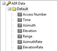
By creating a sample report in the desktop application, you know that the data provider is time varying, and that data provider is located under the AER Data group. The data provider contains 15 columns of data. You can speed up the calculation by requesting only columns that you need.
Execute the element call return results based on the time interval and time step. The “data sets” represent columns of the report. The order of the columns is the same as in the report. The order of the columns requested in the elements array is ignored.
Since the data is returned in the columns format and you can usually work with rows of data, you will create a class that represents the row of data and add the information to the list collection.
Create a vector between the aircraft and facility objects.
|
[C#] |
| //Create vector between objects
IAgCrdnVectorDisplacement vector = (IAgCrdnVectorDisplacement)facility.Vgt.Vectors.Factory.Create("FromTo", "Vector description", AGI.STKVgt.AgECrdnVectorType.eCrdnVectorTypeDisplacement); vector.Destination.SetPoint(satellite.Vgt.Points["Center"]); vector.Origin.SetPoint(facility.Vgt.Points["Center"]); |
|
[Java] |
| //Create vector between objects
IAgCrdnVectorDisplacement vector = (IAgCrdnVectorDisplacement) facility.getVgt().getVectors().getFactory().create("FromTo", "Vector description", AgECrdnVectorType.E_CRDN_VECTOR_TYPE_DISPLACEMENT); vector.getDestination().setPoint(satellite.getVgt().getPoints().getItem("Center")); vector.getOrigin().setPoint(facility.getVgt().getPoints().getItem("Center")); |
|
[MATLAB] |
| %Create vector between objects
vector = facility.Vgt.Vectors.Factory.Create('FromTo', 'Vector description', 'eCrdnVectorTypeDisplacement'); vector.Destination.SetPoint(satellite.Vgt.Points.Item('Center')); |
|
[Python] |
| #Create vector between objects
vector = facility.Vgt.Vectors.Factory.Create('FromTo', 'Vector description', AgSTKVgtLib.eCrdnVectorTypeDisplacement) vector2 = vector.QueryInterface(AgSTKVgtLib.IAgCrdnVectorDisplacement) vector2 = vector.QueryInterface(AgSTKVgtLib.IAgCrdnVectorDisplacement) vector2.Destination.SetPoint(satellite.Vgt.Points.Item('Center')) |
AGI introduced the Vector Geometry Tool (VGT) with STK application version 9. In version 10, VGT became part of the Analysis Workbench that also includes the Time Tool and Calculation Tool. To keep the interface clean and to maintain backward compatibility, all Analysis Workbench functionality is located in the VGT property of the IAgStkObject interface.
While Analysis Workbench provides many built-in objects, it is designed to enable you to create custom elements and perform custom results. As a result, the interface requires an object path as input to access the object.
Visualize the vector and set its size to 4.0:
|
[C#] |
| //Visualize vector
IAgVORefCrdnVector boresightVector = facility.VO.Vector.RefCrdns.Add(AgEGeometricElemType.eVectorElem, "Facility/MyFacility FromTo Vector") as IAgVORefCrdnVector; facility.VO.Vector.VectorSizeScale = 4.0; |
|
[Java] |
| //Visualize vector
IAgVORefCrdnVector boresightVector = (IAgVORefCrdnVector) facility.getVO().getVector().getRefCrdns().add(AgEGeometricElemType.E_VECTOR_ELEM, "Facility/MyFacility FromTo Vector"); facility.getVO().getVector().setVectorSizeScale(4.0); |
|
[MATLAB] |
| %Visualize vector
boresightVector = facility.VO.Vector.RefCrdns.Add('eVectorElem', 'Facility/MyFacility FromTo Vector'); facility.VO.Vector.VectorSizeScale = 4.0; |
|
[Python] |
| #Visualize vector
boresightVector = facility2.VO.Vector.RefCrdns.Add(STKObjects.eVectorElem, 'Facility/MyFacility FromTo Vector') facility2.VO.Vector.VectorSizeScale = 4.0 |
All vectors on the single object are the same size. So, in order to modify the vector’s appearance, you will need to set the global vector properties.
Get local close approach values. Also, take a look at the syntax for the add method. The method requires an object type as an enumeration and a fully qualified path to the Analysis Workbench object. The path consists of the path to the parent object, the object name, and the object type ("Facility/MyFacility FromTo Vector").
Before STK application version 10, the only way to get summary data was to call the Report Connect command and parse the report in order to get summary data.
STK software reports times of the local minimum, so you need to get the vector between objects and calculate the vector’s magnitude for each local minimum time.
|
[C#] |
| //Get built in Calucation object from Analysis Workbench
var parameterSets = access.Vgt.ParameterSets["From-To-AER(Body)"]; //Get magnitude vector IAgCrdnCalcScalar magnitude = ((IAgCrdn)parameterSets).EmbeddedComponents["From-To-AER(Body).Cartesian.Magnitude"] as IAgCrdnCalcScalar; //Get times of the minimum value for each access interval AgCrdnEventArrayExtrema minTimes = ((IAgCrdn)parameterSets).EmbeddedComponents["From-To-AER(Body).Cartesian.Magnitude.TimesOfLocalMin"] as AgCrdnEventArrayExtrema; Array timeArray = minTimes.FindTimes().Times; for (int i = 0; i < timeArray.Length; i++) { double result = magnitude.Evaluate(timeArray.GetValue(i)).Value; } |
|
[Java] |
| //Get built in Calucation object from Analysis Workbench
IAgCrdnParameterSet parameterSets = access.getVgt().getParameterSets().getItem("From-To-AER(Body)"); //Get magnitude vector IAgCrdnCalcScalar magnitude = (IAgCrdnCalcScalar) ((IAgCrdn)parameterSets).getEmbeddedComponents().getItem("From-To-AER(Body).Cartesian.Magnitude"); //Get times of the minimum value for each access interval Object[] timeArray = minTimes.findTimes().getTimes().getJavaObjectArray(); for (int i = 0; i < timeArray.length; i++) { System.out.println(magnitude.evaluate(timeArray[i].toString()).getValue()); } |
|
[MATLAB] |
| %Get built in Calculation object from Analysis Workbench
parameterSets = access.Vgt.ParameterSets.Item('From-To-AER(Body)'); %Get magnitude vector magnitude = parameterSets.EmbeddedComponents.Item('From-To-AER(Body).Cartesian.Magnitude'); %Get times of the minimum value for each access interval minTimes = parameterSets.EmbeddedComponents.Item('From-To-AER(Body).Cartesian.Magnitude.TimesOfLocalMin'); timeArray = minTimes.FindTimes().Times; for i = 1:size(timeArray,1) result = magnitude.Evaluate(cell2mat(timeArray(i))); end |
|
[Python] |
| #Get built in Calculation object from Analysis Workbench
parameterSets = access.Vgt.ParameterSets.Item('From-To-AER(Body)') #Get magnitude vector magnitude = parameterSets.QueryInterface(AgSTKVgtLib.IAgCrdn) magnitude2 = magnitude.EmbeddedComponents.Item('From-To-AER(Body).Cartesian.Magnitude') #Get times of the minimum value for each access interval minTimes = parameterSets.QueryInterface(AgSTKVgtLib.IAgCrdn) minTimes2 = minTimes.EmbeddedComponents.Item('From-To-AER(Body).Cartesian.Magnitude.TimesOfLocalMin') minTimes3 = minTimes2.QueryInterface(AgSTKVgtLib.IAgCrdnEventArray) timeArray = minTimes3.FindTimes().Times magnitude3 = magnitude2.QueryInterface(AgSTKVgtLib.IAgCrdnCalcScalar) for i in range(0,len(timeArray)): result = magnitude3.Evaluate(timeArray[i]) |
Both the magnitude vector and time array are referenced by a long string that can be daunting to enter. The preference is to create an equivalent STK scenario in the desktop application. Then, from the properties of the Analysis Workbench object, you will get the name value that corresponds to the string value in the code.
Future developments of this tutorial
This tutorial currently does not include instructions for the following tasks in the languages specified. Until these tasks are added to this tutorial in a future release, see STK Tutorial Using the Object Model (PDF).
C# - Develop stand alone application with User Interface
C# - Develop stand alone application without User Interface
VB.net - Develop UI Plugin
VB.net - Connect to existing STK Desktop Application instance
VB.net - Create new STK Desktop Application instance
VB.net - Develop stand alone application with User Interface
VB.net - Develop stand alone application without User Interface
Java - Connect to existing STK Desktop Application instance
Java - Create new STK Desktop Application instance
Java - Develop stand alone application with User Interface
Java - Develop stand alone application without User Interface
MATLAB - Connect to existing STK Desktop Application instance
MATLAB - Create new STK Desktop Application instance
MATLAB - Develop stand alone application with User Interface
MATLAB - Develop stand alone application without User Interface
Python - Connect to existing STK Desktop Application instance
Python - Create new STK Desktop Application instance
Python - Develop stand alone application with User Interface
Python - Develop stand alone application without User Interface
JavaScript - Develop HTML page hosted inside the STK application