Wireless Propagation |
When computing Access with DME Component Libraries, links are used to identify the connection between two objects which are communicating with each other in a certain way. One link may represent a spacecraft using optics to observe a target on the ground. Another link may represent the ability of a ground station to track a launch effectively. In the Communications Library, the primary use is to represent a wireless RF signal, given certain physical effects which degrade its fidelity.
The functionality described in this topic requires a license for the Communications Library. |
There are two kinds of links provided with DME Component Libraries: LinkInstantaneous, which models instantaneous communication along the link, and LinkSpeedOfLight, which models the time delay of light traveling along the link. The WirelessLinkExtension takes this time delay into account when evaluating signal propagation. Specifically, when a receiving antenna asks a communication link for its signals, the signals will be transmitted at a time prior to reception as determined by the link. The extension also applies the effects of SignalPropagationModels to the signal before reaching the receiver. Here is a list of some of the models which affect wireless signals, including many based on standards from the International Telecommunication Union (ITU):
FreeSpacePathLossModel - The loss in power associated with the spreading of the electromagnetic wave over large distances.
DopplerShiftModel - The shift in frequency associated with the relative motion of the link.
AtmosphericAttenuationModelItuRP676Version9 - The ITU-R P.676 model (version 9) representing signal attenuation due to atmospheric gasses for links passing through Earth's atmosphere.
CloudFogAttenuationModelItuRP840Version6 - The ITU-R P.840 model (version 6) representing signal attenuation due to cloud cover and dense fog.
TropoScintAttenuationModelItuRP618Version12 - The ITU-R P.618 model (version 12) representing the effects of additional electromagnetic radiation created from the signal interacting with the atmosphere. (also available: version 9)
RainAttenuationModelItuRP618Version12 - The ITU-R P.618 model (version 12) representing signal attenuation from the effects of water precipitation. (also available: version 10)
RainAttenuationModelItuRP838Version3 - The ITU-R P.838 model (version 3) representing signal attenuation from the effects of water precipitation.
CraneRainAttenuationModel - The Crane model representing the attenuation due to the effects of water precipitation.
SimpleSatcomAtmosphericAttenuationModel - The SATCOM model representing signal attenuation from propagating through Earth's atmosphere.
TropoScintAttenuationModelItuRP1814 - The ITU-R P.1814 scintillation attenuation model representing the attenuation due to scintillation effects for a plane wave and weak turbulence.
BeerLambertLawAtmosphericAttenuationModel - An atmospheric absorption model based on the Beer-Lambert Law.
Custom - By extending SignalPropagationModel and implementing a corresponding SignalPropagator, users can apply custom effects onto the signal during propagation.
Once all the links are configured, they should then be added to a SignalPropagationGraph. This keeps track of which transmitters are relevant to which receivers in order to define how signals are propagated from one platform to another. The SignalPropagationGraph is then used to create SignalEvaluators, as well as constraints and figures of merit. One benefit of the SignalPropagationGraph type is that it allows the user to set up multiple communication scenarios with different transmitters and link paths within the same EvaluatorGroup.
The SignalPropagationGraph plays an important role in informing the receivers which signals to process. The following figure illustrates a SignalPropagationGraph with multiple transmitters and interference.
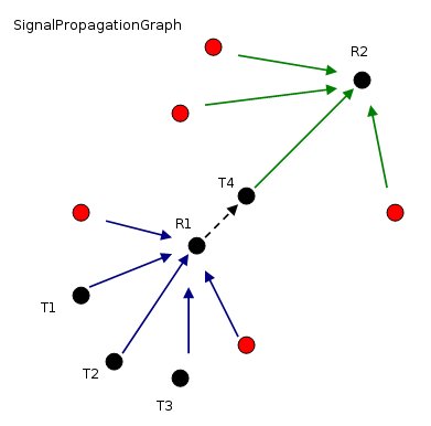
There are four intended transmitters, two receivers, and five transmitters which act solely as interference. When the library asks Receiver 2 to output signals, the receiver asks the SignalPropagationGraph for all the links (shown in green) coming into the receiver. At this stage, there is no distinction made between "intended" and "interfering" signals. Moreover, when Transmitter 4 acts as a transponder for Receiver 1, Receiver 1 asks the SignalPropagationGraph for all the links shown in blue. Unless any of those signals are eliminated by a filter between Receiver 1 and Transmitter 4, Transmitter 4 will retransmit the interference along with the intended signals. Ultimately, an IntendedSignalStrategy is needed to distinguish the intended signal. When the signal originating at Transmitter 1 is identified as the intended signal, the signals from Transmitter 2 and Transmitter 3 will be treated as interference. Likewise, when Transmitter 2 creates the intended signal, Transmitter 1 and Transmitter 3 are treated as interference.
SignalPropagationGraph signalPropagation = new SignalPropagationGraph();

WirelessLinkExtension downlinkExtension = new WirelessLinkExtension();
// Add Propagation Models
// Note that the propagation models are applied in order.
// So, if a model is to be computed before doppler and/or freespace loss,
// make sure it is in the correct place in the list.
downlinkExtension.PropagationModels.Insert(0, new AtmosphericAttenuationModelItuRP676Version9());
downlinkExtension.PropagationModels.Add(new RainAttenuationModelItuRP618Version12());
LinkSpeedOfLight downlink = new LinkSpeedOfLight(downlinkXmtr, rcvrPhiladelphia, earth.InertialFrame);
downlink.Extensions.Add(downlinkExtension);
// The link doesn't propagate a signal through the Earth
downlink.Extensions.Add(new AccessConstraintsExtension(new CentralBodyObstructionConstraint(downlink, earth)));
signalPropagation.AddLink(downlink);

// Add the uplinks
LinkSpeedOfLight uplinkOne = new LinkSpeedOfLight(transmitterOne, uplinkRcvr, earth.InertialFrame);
// Reuse the list of propagation models
WirelessLinkExtension wirelessExtension = new WirelessLinkExtension(downlinkExtension.PropagationModels);
uplinkOne.Extensions.Add(wirelessExtension);
uplinkOne.Extensions.Add(new AccessConstraintsExtension(new CentralBodyObstructionConstraint(uplinkOne, earth)));
signalPropagation.AddLink(uplinkOne);
LinkSpeedOfLight uplinkTwo = new LinkSpeedOfLight(transmitterTwo, uplinkRcvr, earth.InertialFrame);
// Reuse the list of propagation models
wirelessExtension = new WirelessLinkExtension(downlinkExtension.PropagationModels);
uplinkTwo.Extensions.Add(wirelessExtension);
uplinkTwo.Extensions.Add(new AccessConstraintsExtension(new CentralBodyObstructionConstraint(uplinkTwo, earth)));
signalPropagation.AddLink(uplinkTwo);
LinkSpeedOfLight uplinkThree = new LinkSpeedOfLight(transmitterThree, uplinkRcvr, earth.InertialFrame);
// Reuse the list of propagation models
wirelessExtension = new WirelessLinkExtension(downlinkExtension.PropagationModels);
uplinkThree.Extensions.Add(wirelessExtension);
uplinkThree.Extensions.Add(new AccessConstraintsExtension(new CentralBodyObstructionConstraint(uplinkThree, earth)));
signalPropagation.AddLink(uplinkThree);

// Add the uplink interferers
foreach (Platform interferer in uplinkInterferers)
{
    LinkSpeedOfLight link = new LinkSpeedOfLight(interferer, uplinkRcvr, earth.InertialFrame);
    // just use free space loss and doppler shift by default
    wirelessExtension = new WirelessLinkExtension();
    link.Extensions.Add(wirelessExtension);
    link.Extensions.Add(new AccessConstraintsExtension(new CentralBodyObstructionConstraint(link, earth)));
    signalPropagation.AddLink(link);
}

// Add the downlink interferers
foreach (Platform interferer in downlinkInterferers)
{
    LinkSpeedOfLight link = new LinkSpeedOfLight(interferer, rcvrPhiladelphia, earth.InertialFrame);
    // just use free space loss and doppler shift by default
    wirelessExtension = new WirelessLinkExtension();
    link.Extensions.Add(wirelessExtension);
    link.Extensions.Add(new AccessConstraintsExtension(new CentralBodyObstructionConstraint(link, earth)));
    signalPropagation.AddLink(link);
}

IntendedSignalStrategy strategy = new IntendedSignalByModulation<ModulationQpsk>(frequencyForDownlink);
// Use the propagation graph and the intended signal strategy to compute parameters at the receiver
ScalarCarrierToNoise carrierToNoise = new ScalarCarrierToNoise(rcvrPhiladelphia, signalPropagation, strategy);
// To evaluate parameters at the receiver, apply a delay to scalars which occur at different points
// along the signal propagation path.
Scalar effectiveIsotropicRadiatedPower = new ScalarDelayedByLink(
    new ScalarEffectiveIsotropicRadiatedPower(downlink, signalPropagation, strategy),
    downlink, LinkRole.Receiver);
// Create evaluators
EvaluatorGroup group = new EvaluatorGroup();
ScalarEvaluator cnrEvaluator = carrierToNoise.GetEvaluator(group);
ScalarEvaluator eirpEvaluator = effectiveIsotropicRadiatedPower.GetEvaluator(group);
group.OptimizeEvaluators();