Modeling a System with a Block Definition Diagram
Overview
When modeling a system or system of systems in SysML, you should start by creating a block definition diagram (BDD). A BDD is simply a view of the structural elements of your system (the blocks) and their relationships with one another. In this section, you will create a high-level BDD that models an Unmanned Aerial Vehicle (UAV), its power system, and its onboard computer.
This section covers the following concepts:
- Block definition diagrams
- Blocks
- Inheritance
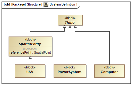
Figure A1: A block definition diagram
Prerequisites
| Prerequisite | Description |
|---|---|
| Moxie Installation | You must have installed Moxie. |
| Tutorial Project | You must start this section with a new Moxie simulation project, as created in the previous section. If you did not complete that part of the previous section, you can use the following project from the Moxie installation: \documentation\tutorialFiles\01\MoxieProjectConfiguration.mdzip |
| Recommended Reading | Before completing this section, you may want to read the following help topics: |
Instructions
Create a block definition diagram
As a best practice, you should place structural elements such as BDDs and their corresponding blocks in a Structure package.
- Open the project from the previous section.
- In the Containment Tree, right-click the top-level Model and select Create Element (or press ).
-
In the General category,
select Package,
enter
Structureas its name and press . - Right-click the Structure package and select Create Diagram (or press ).
-
In the SysML Diagrams category,
select SysML Block Definition Diagram,
enter
System Definitionas its name, and press . You may need to click the button in the lower left of the dialog in order to find SysML Block Definition Diagram.
Create a block for a UAV
Any block that owns behaviors you wish to simulate must either directly or indirectly derive from
Moxie-Base::Structure::Thing.
So as a best practice, you should specify Moxie-Base::Structure::Thing as the
Base Classifier for all your SysML blocks.
Though this is not required, doing so will not cause any problems and will likely prevent debugging headaches as your simulation becomes more
complex.
At a high-level, a UAV is simply an entity that moves through space and time.
Deriving the UAV block from Moxie-Core::Structure::SpatialEntity
not only allows you to simulate behaviors of the UAV because SpatialEntity derives from
Moxie-Base::Structure::Thing,
it also provides you with convenient properties and operations for calculating its distance to other spacial entities or spatial points in your
model.
-
Drag the Moxie-Core > Structure >
SpatialEntityblock onto the BDD. -
In the BDD,
you should now see the
SpatialEntityblock and possibly theThingblock from which it derives. If you do not see theThingblock, right-click theSpatialEntityblock, select Display > Display Related Elements, ensure Generalization is selected, and click . -
Select the
SpatialEntityblock, click the downward-pointing Generalization button ( ) on the context toolbar next to the
block,
then click anywhere on the canvas to add a new block.
) on the context toolbar next to the
block,
then click anywhere on the canvas to add a new block.
-
Double-click the new block to open its specification window,
enter
UAVas its Name, and click .
Each block in the Moxie-Base and Moxie-Core packages includes comprehensive documentation. To view this documentation, select Documentation/Comments from the left pane of the block's specification window.
Create blocks for the UAV's components
The Moxie models do not include any classifier that corresponds directly to the concept of a power system or of a computer,
so the blocks for those subsystems should just derive directly from Moxie-Base::Structure::Thing.
You do not need to worry about connecting them to the UAV block right now;
you will add relationships in the next section.
-
In the BDD,
select the
Thingblock, click the downward-pointing Generalization button () on the context toolbar next to the
block,
then click anywhere on the canvas to add a new block.
-
Double-click the new block to open its specification window,
enter
PowerSystemas its Name, and click . -
Select the
Thingblock again, click the downward-pointing Generalization button () on the context toolbar next to the
block,
then click anywhere on the canvas to add a new block.
-
Double-click the new block to open its specification window,
enter
Computeras its Name, and click .Figure B1: The block definition diagram
- Save your work before continuing.
Next Section >